
This tutorial demonstrates the validity of the FWM algorithm, as well as providing the user with some useful designing tips for optimizing simulation time and accuracy.
The layout in was used to obtain results, and can be found in the sample file FWM Validation.osd

Figure 1: FWM project layout
In the two CW Lasers, the frequencies are set to 1540 and 1540.5 nm, power set to 0 dBm, and the linewidth set to 0 (see Figure 2). The linewidth is set to 0 is because we are only interested in measuring the total power of the sideband frequencies, so the shape of the spectrum is not required.
The channels were then multiplexed together using a 2×1 Mux.
After the Mux, the signals are propagated through 75 km of nonlinear fiber, where they experience the effects of Attenuation, Group Velocity Dispersion (GVD), and FWM.
The setup for the SMF-28 fiber component can be see from Figure 3 through to Figure 6.

Figure 2: CW Laser properties dialog box
You can see in Figure 3 that the input and output coupling efficiencies are set to 0.

Figure 3: SMF-28 fiber properties dialog box—Main tab
In Figure 4, the GVD parameter was set to 1 ps/nm/km, so that it follows the example in [1].

Figure 4: SMF-28 fiber properties dialog box—Dispersion tab
In Figure 5, you will see that the Effective Area was set to 64μ2, and the n2 constant to 4.3286e-21.
The n2 constant was calculated using the following equation:
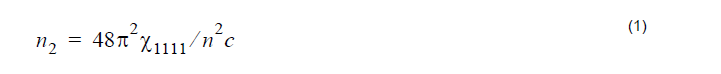
where X1111 is the third-order nonlinear susceptibility, n is the refractive index, and
c is the speed of light.
Now, X1111 = 6e – 15m3 / W / s, n = 1.48, c = 3e8m / s .
Therefore,


Figure 5: SMF-28 fiber properties dialog box—Nonlinear tab

Figure 6: SMF-28 fiber properties dialog box—Numerical tab
If you calculate the project, you will obtain the results see in Figure 7 and Figure 8.

Figure 7: Input optical spectrum

Figure 8: Output optical spectrum
If you zoom in on the FWM sidebands, you will find that the power is approximately -72.7 dBm, compared to -72.3 as predicted by [1].
Reference:
[1]G. Keiser, Optical Fiber Communications 3rd Edition, Example 12-8. pp. 499, (2000)