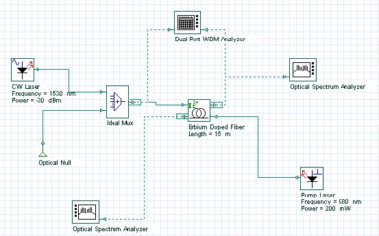
The amplifier performance characterized by the signal output power, gain and noise figure depends on the pump wavelength. The project file “Pumping requirements.osd” shown in two different layouts, “Pump power 980 nm” and “Pump power 1480 nm”, details an amplifier pumped by 980 nm and 1480 nm. The 980 nm and 1480 nm pump wavelengths are the most important ones used in EDFAs. Figure 1 shows the layout setup in a co-propagating pump scheme with 980 nm and 1480 nm wavelength pumps.
Figure 1: Amplifier setup in a co-propagating pump scheme used with 980 nm and 1480 nm wavelength pump
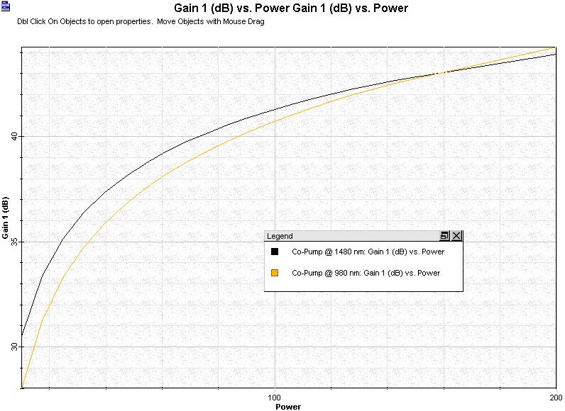
High amplifier gains in the range 30-40 dB can be obtained in this project file, sweeping the pump power from 10 mW to 200 mW. The signal input power considered in this case is -20 dBm. Output power calculated in this project is in the range 6 – 17 dBm, while the noise figure varied between 3 – 5 dB. Different signal input power or signal wavelength as well as fiber parameters can be set in this example and the new results can be compared with previous one. Results obtained with these layouts are shown in Figure 2. New Erbium-doped fiber data can be used in this case and results compared. The cross-section or Giles parameters need to be updated as well as the fiber dimension and doping characteristics.
EDFAs can be designed to operate in such a way that the pump and signal beams propagate in opposite directions, a configuration referred to as backward pumping to distinguish it from forward-pumping configuration in which both beams propagate along the same direction. Backward or counter-propagating pump scheme is exemplified in the layout “Backward pump @ 980 nm”. The pump power is swept from 10 to 150 mW and the signal input power is -20 dBm.
Figure 2: Gain versus pump power considering a co-propagating pump schemes @ 980 nm and @ 1480 nm wavelength pump
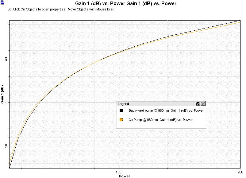
The layout considering backward or counter-propagating pump scheme is shown in Figure 3. Figure 4 shows the gain versus pump power when 980 nm and 1480 nm are considered as wavelength pump. The influence of the selected pump scheme in the amplifier performance can be checked considering unsaturated or saturated regime just changing the signal input power range.
Figure 3: Amplifier setup in counter-propagating pump scheme used with 980 nm and 1480 nm wavelength pump
Figure 4: Gain versus pump power considering a co-propagating pump schemes @ 980 nm and @ 1480 nm wavelength pump
The layout Bidirectional pump @ 980 nm added to this project file considers the bidirectional pumping configuration, where the amplifier is pumped in both directions simultaneously by using to semiconductor pump lasers located at the two fiber ends. The advantage of this pump scheme can be checked setting small-signal or large signal input and observing the amplifier performance given by the gain, output power and noise figure graphs displayed in Views.


