In this tutorial we show an example of a maximization procedure. We will optimize the launch power and DCF length to maximize the Q factor at the receiver.
Upgrading an existing noise-limited fiber plant requires an increase in launched power, which in turn brings the fiber nonlinearities. It has been shown that nonlinear return to zero (RZ) coding offers significant advantages for high bit rate transmission systems [1][2]. Because the fiber dispersion and Kerr nonlinearities balance each other in this case, the launched power is not limited by self phase modulation (SPM). But this configuration requires careful selection of launch power and dispersion compensating fiber (DCF) length.
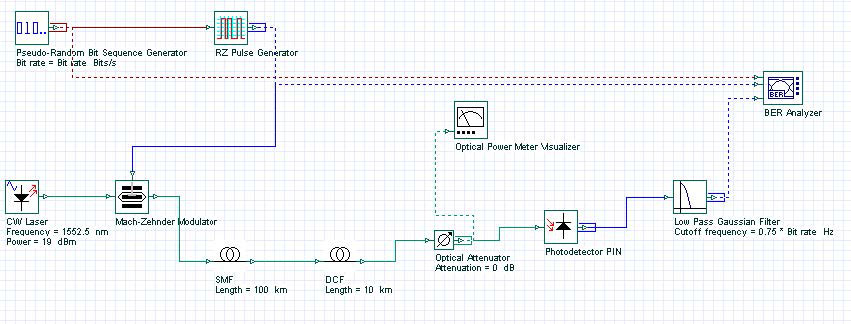
Figure 1 shows the project layout. SMF fiber parameters are as follows: Attenuation is 0.171 dB/km, dispersion is 17.7 ps/nm/km, effective area is 80 micron square, n2 = 2.7×10⁻²⁰ m2/W, length is 100 km.
DCF fiber parameters are as follows: Attenuation is 0.6 dB/km, dispersion is -80 ps/nm/km, effective area is 30 micron square, n2 = 3×10-20 m2/W, length is 100 km [3]. Bit rate is 10 Gbps, 7th order PRBS bit sequence and Gaussian beam profile is used. The receiver sensitivity is -17 dBm.
The receiver sensitivity is -17 dBm. An attenuator is used to find the power penalty. Attenuation of the attenuator is initially set to 0 when the optimization is performed. Later, another optimization is carried out to find the power penalty by comparing back- to-back performance transmission and link performance. This is done by varying the attenuation of the attenuator to get the same Q factor (6) as we got from back-to-back transmission. The received power (Preceived) is then compared with the receiver sensitivity to find the power penalty.
Power penalty is given as Ppenalty (dB) = -17 dBm – Preceived (dBm).
Figure 1: Project layout
Parameters for the optimization tool are as follows: Initial laser power and DCF length are set to 20 dBm and 20 km respectively. Lower and upper bounds of power are defined as 15 dBm and 25 dBm, 0 and 30 km for DCF length. The termination tolerance of the parameter is 1, that of the result is 0.1.
The Maximum Q Factor is obtained after 15 calculations, when the laser power is about 19 dBm and DCF length is about 10 km. At the optimum point, the Maximum Q Factor is ~20. Received average power is -8.25 dBm.
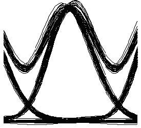
Figure 2: Eye diagram for RZ modulation with optimum parameters
Maximum Q Factor for back-to-back propagation was about 68. This shows that the optimum dispersion compensation corresponds to about 45 km of compensated SMF (~963 ps/nm residual dispersion) with ~20 dBm launch (~16 dBm average) power. We also found that the power penalty at 10-9 BER is 0 dB for optimum values (Required received power to get 10-9 BER is around -17 dBm, which is same as the receiver sensitivity). Figure 2 shows the eye diagram after 100 km of propagation with optimum parameters.
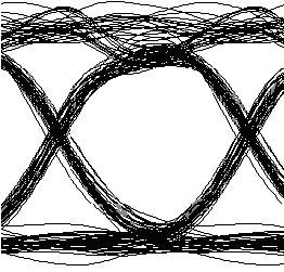
Figure 3: Eye diagram for NRZ modulation with optimum parameters
In [3], it has been shown that similar results can be obtained from a NRZ modulation format for a single span system, by leaving the correct amount of residual dispersion in the system. In this case, the optimum residual dispersion is lower than that of RZ case.
We have performed similar optimizations for NRZ modulations. The receiver sensitivity is -15.6 dBm. Maximum Q is obtained after 4 calculations when laser power is ~19 dBm (~16 dBm average power), and DCF length is ~18 km. At the optimum point, Maximum Q Factor is ~10 and received average power is -12.3 dBm.
We have found that the power penalty at 10-9 BER is ~1 dB for the optimum values when NRZ is used. Optimum dispersion compensation corresponds to about 80 km of compensated SMF (~355 ps/nm residual dispersion).
Figure 3 shows the eye diagram after 100 km of propagation with optimum parameters when NRZ modulation format is used. The obtained results agree well with the experimental findings of [3] and [4]. Furthermore, comparing the Q factors at optimum points shows that, in fact RZ modulation can tolerate more distortion and reach longer transmission distance.
References:
[1] M. L. Dennis, et al., “Long span repeaterless transmission using adiabatic solitons”, IEEE Photon. Tech. Lett. 11, 478 (1999).
[2] C. Furst., et al., “Performance limits of nonlinear RZ and NRZ coded transmission at 10 and 40
Gb/s on different fibers”, OFC 2000 2, WM31-302 (2000).
[3] C. Furst, et al., “RZ verses NRZ coding for 10Gbit/s amplifier free transmission”, LEOS 1999 1, MJ1-82 (1999).
[4] G. Mohs, et al., “Advantages of nonlinear RZ over NRZ on 10 Gb/s single-span links”, OFC
2000, FC2-35 (2000).


