Optiwave software can be used in different industries and applications, including Fiber Optic Communication, Sensing, Pharma/Bio, Military & Satcom, Test & Measurement, Fundamental Research, Solar Panels, Components / Devices, etc..
OptiSystem is a comprehensive software design suite that enables users to plan, test, and simulate optical links in the transmission layer of modern optical networks.
OptiSPICE is the first circuit design software for analysis of integrated circuits including interactions of optical and electronic components. It allows for the design and simulation of opto-electronic circuits at the transistor level, from laser drivers to transimpedance amplifiers, optical interconnects and electronic equalizers.
OptiFDTD is a powerful, highly integrated, and user friendly CAD environment that enables the design and simulation of advanced passive and non-linear photonic components.
OptiBPM is a comprehensive CAD environment used for the design of complex optical waveguides. Perform guiding, coupling, switching, splitting, multiplexing, and demultiplexing of optical signals in photonic devices.
OptiFiber The optimal design of a given optical communication system depends directly on the choice of fiber parameters. OptiFiber uses numerical mode solvers and other models specialized to fibers for calculating dispersion, losses, birefringence, and PMD.
Emerging as a de facto standard over the last decade, OptiGrating has delivered powerful and user friendly design software for modeling integrated and fiber optic devices that incorporate optical gratings.
OptiConverge is a collaborative integration framework that seamlessly combines two or more Optiwave products (e.g., OptiSystem, OptiSPICE, OptiFDTD, etc.) and other third party products into unified solutions. Designed to streamline complex workflows, it empowers users to achieve their goals faster by harnessing the collective power of our trusted Optiwave tools.
The frequency response of an LED is determined by the carrier dynamics (and therefore is limited by the carrier lifetime Tn) and the parasitic capacitance of the LED (described by the RC constant TRC[2].
If a small, constant forward bias is applied, the influence of the parasitic capacitance of the LED can be neglected. The LED 3-dB modulation optical bandwidth is defined as the modulation frequency at the LED power transfer function is reduced by 3 dB [1]. The LED 3-dB modulation optical bandwidth could be expressed as:
ƒ3dB = √3 / 2π / (Tn + TRCn).
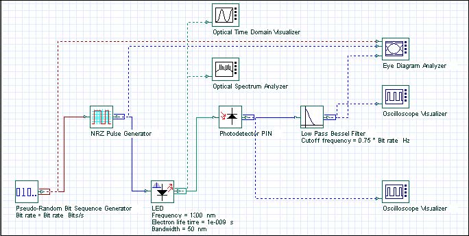
We would like to demonstrate the modulation response properties of the LED. The project is depicted in Figure 1.
Figure 1: Project layout
The default values of the carrier lifetime Tn and the RC constant TRC, are 1 ns and
1 ns, respectively. Therefore, the ƒ3dB is approximately 140 MHz.
Discussion of the numerical parameters: for example, bit rate is 300 Mb/s and sequence length 128 bits, therefore, the time window is about 430 ns. Samples per bit are 256, therefore, the sample rate is 76 GHz. The default resolution therefore is about 2 MHz.
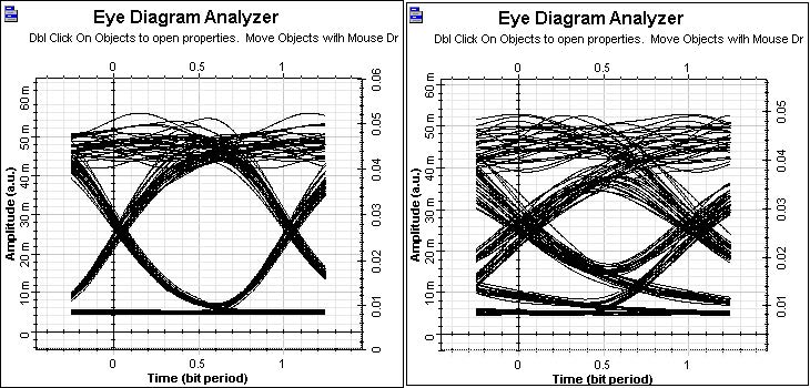
Let us first keep the carrier lifetime Tn and the RC constant TRC, which means ƒ3dB
is about 140 MHz, and analyze the closure of the eye diagram as a measure for the
performance of the system. The results for 100Mb/s and 300Mb/s transmission are
shown in Figure 2.
Figure 2: System performance with increased bit rate
Clearly the performance of the digital system is considerably worsened by increasing the bit rate above the LED 3-dB modulation optical bandwidth.
The influence of the modulation response of the LED can be studied also by keeping
the bit rate, for example 300 Mb/s, and reducing the carrier lifetime Tn and the RC
constant TRC, therefore increasing ƒ3dB . Let us assume Tn = TRC = 0.5ns,
therefore ƒ3dB will be about 280MHz.
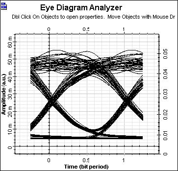
A large improvement in the system performance at 300 Mb/s compared to the latest figure should be seen. This is illustrated in Figure 3.
Figure 3: Improved system performance at 300Mb/s
References
[1]G.P. Agrawal, Fiber-Optic Communication Systems, Joinery & Sons, Inc, second edition, 1997.