Optiwave software can be used in different industries and applications, including Fiber Optic Communication, Sensing, Pharma/Bio, Military & Satcom, Test & Measurement, Fundamental Research, Solar Panels, Components / Devices, etc..
OptiSystem is a comprehensive software design suite that enables users to plan, test, and simulate optical links in the transmission layer of modern optical networks.
OptiSPICE is the first circuit design software for analysis of integrated circuits including interactions of optical and electronic components. It allows for the design and simulation of opto-electronic circuits at the transistor level, from laser drivers to transimpedance amplifiers, optical interconnects and electronic equalizers.
OptiFDTD is a powerful, highly integrated, and user friendly CAD environment that enables the design and simulation of advanced passive and non-linear photonic components.
OptiBPM is a comprehensive CAD environment used for the design of complex optical waveguides. Perform guiding, coupling, switching, splitting, multiplexing, and demultiplexing of optical signals in photonic devices.
OptiFiber The optimal design of a given optical communication system depends directly on the choice of fiber parameters. OptiFiber uses numerical mode solvers and other models specialized to fibers for calculating dispersion, losses, birefringence, and PMD.
Emerging as a de facto standard over the last decade, OptiGrating has delivered powerful and user friendly design software for modeling integrated and fiber optic devices that incorporate optical gratings.
OptiConverge is a collaborative integration framework that seamlessly combines two or more Optiwave products (e.g., OptiSystem, OptiSPICE, OptiFDTD, etc.) and other third party products into unified solutions. Designed to streamline complex workflows, it empowers users to achieve their goals faster by harnessing the collective power of our trusted Optiwave tools.
Extracting the Thermal Noise Parameter for a Specific Receiver Sensitivity
Home » Tutorials » Extracting the Thermal Noise Parameter for a Specific Receiver Sensitivity
Compatibility:
In this tutorial, we provide a basic example of Goal Attainment optimizations. In this example we will use the optimization tool in the context of parameter extraction. Thermal noise parameter of PIN will be extracted to get a receiver sensitivity of -17 dBm.
The design layout is shown in Figure 1. The transmitter power is selected to be 0 dBm. The bit rate is 10 Gbps and average received power is about -17 dBm when attenuation is 14.5 dB.
Figure 1: Project layout for the extraction of thermal noise parameter of PIN
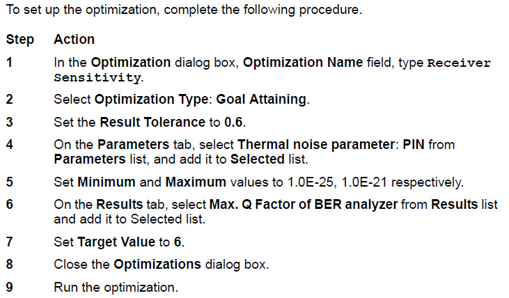
Setting up the optimization
After about 3 passes, the optimizer will find the Thermal noise parameter to get a Q factor of 6 when received average power is -17 dBm. The proper Thermal noise is found to be 5E-22 W/Hz. The eye diagram in this case is shown in Figure 2. Figure 3 shows the Max. Q factor, respect to received power. This figure is obtained by sweeping the transmitter power from -3 dBm to 4 dBm.
Figure 2: Thermal noise factor of PIN is 5E-22 W/Hz with received average signal power -17 dBm