Optiwave software can be used in different industries and applications, including Fiber Optic Communication, Sensing, Pharma/Bio, Military & Satcom, Test & Measurement, Fundamental Research, Solar Panels, Components / Devices, etc..
OptiSystem is a comprehensive software design suite that enables users to plan, test, and simulate optical links in the transmission layer of modern optical networks.
OptiSPICE is the first circuit design software for analysis of integrated circuits including interactions of optical and electronic components. It allows for the design and simulation of opto-electronic circuits at the transistor level, from laser drivers to transimpedance amplifiers, optical interconnects and electronic equalizers.
OptiFDTD is a powerful, highly integrated, and user friendly CAD environment that enables the design and simulation of advanced passive and non-linear photonic components.
OptiBPM is a comprehensive CAD environment used for the design of complex optical waveguides. Perform guiding, coupling, switching, splitting, multiplexing, and demultiplexing of optical signals in photonic devices.
OptiFiber The optimal design of a given optical communication system depends directly on the choice of fiber parameters. OptiFiber uses numerical mode solvers and other models specialized to fibers for calculating dispersion, losses, birefringence, and PMD.
Emerging as a de facto standard over the last decade, OptiGrating has delivered powerful and user friendly design software for modeling integrated and fiber optic devices that incorporate optical gratings.
OptiConverge is a collaborative integration framework that seamlessly combines two or more Optiwave products (e.g., OptiSystem, OptiSPICE, OptiFDTD, etc.) and other third party products into unified solutions. Designed to streamline complex workflows, it empowers users to achieve their goals faster by harnessing the collective power of our trusted Optiwave tools.
Home » Tutorials » Analysis of Gain and Noise in Erbium doped fiber
Compatibility:
This lesson demonstrates the performance of an amplifier (gain and noise) based on Giles and Desurvire [1] reference.
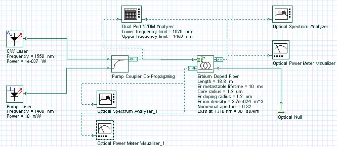
Figure 1: Layout of the system considered in the analysis of gain and ASE
The characteristics of noise and gain presented in Figure 4.b [1] are reproduced through the system shown in Figure 1.
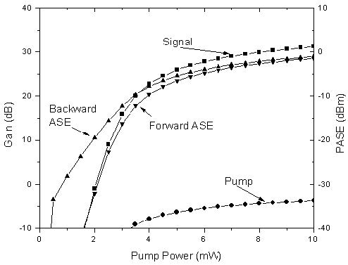
Figure 2 shows gain of pump and signal, and the power of backward and forward ASE as a function of the pump power. The parameters used in this simulation are displayed at Figure 1 and they are similar to the values presented in Table 1 [1], except for the values of the absorption and emission cross sections. Nevertheless, the results found are in good qualitative agreement with the paper.
Figure 2: Amplifier gain and ASE power versus pump for an Er3+-doped fiber amplifier
Note: Figure 2 equivalent to Figure 4 b) [1]
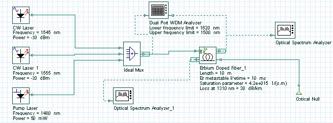
In this second case, the saturation effect of an amplifier is shown using two wavelength multiplexed signals at 1545 nm and 1555 nm. The system layout is shown in Figure 3 and the parameters used are similar to the parameters in Table II [1].
Figure 3: Layout of the system used to demonstrate the saturation of the amplifier
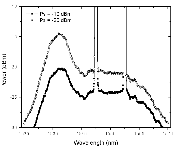
Figure 4 shows the gain compression in the two signals due to the increase in the input power, causing the saturation of the amplifier.
Figure 4: Output spectra of a two channel amplification of a saturated amplifier
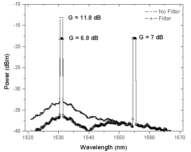
In the next case, the amplifier has two stages and a filter is inserted between the stages (see Figure 5). The effects of the equalization in the ASE are demonstrated.
Figure 5: Layout of the system used to demonstrate gain equalization in the amplifier
The EDF parameters used in this simulation are the same as in the previous case. A filter centered at 1931 nm is introduced in the middle of the EDF in a way that equalizes the gain of the two channels. Figure 6 shows the results with and without the filter. This figure is equivalent to Figure 7 in [1].
Figure 6: Amplifier gain-leveling with a filter centered at 1531 nm
The results of this lesson demonstrated a qualitative agreement with the results obtained by Giles and Desurvire in [1], considered to be one of the most important references in the EDFA modeling.
Reference:
[1]C. Randy Giles, and Emmanuel Desurvire, “Modeling Erbium-Doped Fiber Amplifiers”. IEEE Journal of Lightwave Technology, Volume: 9 Issue: 2, Feb. 1991, Page(s): 271 – 283.