
The fundamental limitation to high- speed communication systems over the embedded standard single-mode fiber at 1.55 mm is the linear chromatic dispersion.
Typical value of β2 = –20ps2/km at 1.55 µm for SMF leads to D=16 ps/(nm.km). For bit rate B = 40 Gb/s, the slot duration will be TB = 25 ps. If we consider the duty cycle
0.5 → TFWHM = 12.5ps → T0 = 7.5ps
the corresponding dispersion length will be approximately LD ~ 2.8 km.
This lesson demonstrates the following:
- Compare RZ- and NRZ- modulation format transmission in SMF at 40 Gb/s taking into account: group velocity dispersion, self-phase modulation due to the Kerr nonlinearity, linear losses, and periodical amplification with ASE noise. The large group velocity dispersion is compensated for with a post-dispersion compensation scheme.
- Analyze the influence of accumulated amplifier noise and self-phase modulation for RZ -modulation format transmission in SMF at 40 Gb/s.
- Compare post-dispersion and pre-dispersion compensation schemes for RZ – modulation format transmission in SMF at 40 Gb/s.
Figure 1 and Figure 2 show the layouts used for observing the RZ- and NRZ- modulation formats.

Figure 1: RZ layout — modulation format

Figure 2: NRZ layout — modulation format
The setup mode Set bit rate with following global parameters was used:
- Bit rate = 40 Gb/s
- Sequence length = 128 Bits
- Samples per bit = 128
Therefore:
- Number of samples = Sequence length * Samples per bit = 16384
- Time window = Sequence length * Bit slot = 3.2 ns
- Sampling interval = Time window / Number of samples = 0.195 ps
- Sample rate = 1 / the sampling interval = 5.12 THz
There are no changes in pseudo-random bit sequence generators in either layout. The RZ- generator has the following properties:
- Rectangle shape: Gaussian
- Duty cycle = 0.5 bit
- Rise time = 0.15 bit
- Fall time = 0.25 bit
An externally modulated CW Laser with carrier wavelength λ =1550 nm and line width = 0.1 MHz was used as the optical source.
Standard mode optical fiber has the following properties:
Dispersion coefficient
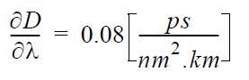
Dispersion slope
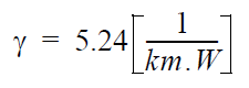
Nonlinear coefficient
Linear losses
α = 0.2 dB/km
Fiber length
LSMF = 50 km
After each segment from SMF, an amplifier compensates the linear losses.
Dispersion compensation fiber has the following properties:
Dispersion coefficient
Dispersion slope
Nonlinear coefficient
Linear losses
α = 0.5 dB/km
Fiber length
LDCF = 10 km
After each segment from DCF, an amplifier compensates the linear losses.
Properties of Bessel optical filter are carrier wavelength &Lambda =1550 nm and bandwidth = 4 x Bit rate.
The cutoff frequency of the low pass Bessel electrical filter is 0.75 x Bit rate.
Ideal periodical amplification is performed with the help of the OptiSystem Ideal EDFA component, which also takes ASE noise into account. The amplifier after SMF has a gain of 10 dB and noise figure of 6 dB. (This after DCF with 5 dB gain and the same noise figure.)
Note the complete dispersion compensation of the GVD of the standard-mode fiber and the complete compensation of the power losses in both fibers. The post- compensation scheme for the dispersion compensation is used. Some of above parameters are chosen in accordance with [1], which allows comparison of results.
In the first part of this lesson, the comparison of RZ and NRZ formats was observed. Figure 3 shows the results obtained with high-dispersion fibers 40 Gbps in SMF RZ.osd for 40 Gb/s RZ modulation format (duty ratio = 0.5) transmission over common distance: from 500 km SMF (10 loops x 50 km) and periodical amplification after each fiber. The dependence of the max Q from the input power is shown in the graph. The BER Analyzer eye diagram represents the optimal point, which according to the graph, is input power ~ 4 mW.

Figure 3: 40 Gbps in SMF RZ results
A well-expressed maximum in the first graph can be seen.
Note: We have not performed any fitting of this curve.
At distances greater than 500 km, max Q becomes smaller than 6. Therefore, this is the maximum distance with good Q performance.
Figure 4 shows the results obtained with high-dispersion fibers 40 Gbps in SMF NRZ.osd for 40 Gb/s NRZ modulation format transmission over common distance from 250 km SMF (5 loops x 50 km) and periodical amplification after each fiber. The dependence of the max Q from the input power is shown in the graph. The BER Analyzer eye diagram represents the optimal point, which according to the graph, is input power ~ 1.25 mW.

Figure 4: 40 Gbps in SMF NRZ results
A well-expressed maximum in the first graph can be seen.
Note: We have not performed any fitting of this curve.
At distances greater than 250 km, max Q becomes smaller than 6. Therefore, this is the maximum available distance with good Q performance.
Comparing positions of the maximums of the two curves, we can clearly see the shift toward greater input powers for the RZ format. The results show that the RZ- modulation format duty cycle = 0.5 is superior to the conventional NRZ- modulation format.
In the second part of this lesson, the influence of accumulated amplifier noise and self-phase modulation on the RZ-modulation transmission in SMF at 40 Gb/s will be analyzed. Two different situations will be considered:
- self-phase modulation is assumed zero
- noise figure is not taken into account
Figure 5 shows the results.

Figure 5: Transmission distance 500 km at 40 Gb/s
At low power levels, the performance is mainly hampered by the accumulated amplifier noise. At high input power levels, the transmission distance is significantly reduced due to the self-phase modulation. Just these effects determine the well- expressed maximum in the Q curve in the first figure.
In the third part of this lesson, two dispersion compensation schemes will be studied
(with high-dispersion fibers 40 Gbps in SMF RZ pre):
- post-compensation
- pre -compensation
Figure 6 shows the project layout.

Figure 6: 40 Gbps in SMF RZ pre-compensation layout
Figure 7 shows the corresponding results for the RZ-modulation transmission in SMF at 40 Gb/s.

Figure 7: RZ modulation format transmission at 40 Gb/s over 500 km in SMF
The results indicate that the post-compensation scheme is superior compared to the pre-compensation scheme in dispersion compensated systems at 40 Gb/s in SMF.
This lesson demonstrated that for upgrading the existing standard fiber network at
1.55 mm at 40 Gbps:
- Dispersion compensation is necessary
- RZ-modulation is superior compared to conventional NRZ-modulation format
- At low power levels, the performance is mainly hampered by the accumulated amplification
- At higher input powers, the transmission distance is significantly reduced by nonlinear self-phase modulation
- Post-compensation scheme is superior compared to pre-compensation scheme. The results agree well with the results of [1], [2], and [3].
References:
1 D. Breuer and K. Petermann, “Comparison of NRZ and RZ- Modulation Format for 40 Gbit/s TDM Standard-Fiber System,” IEEE Photonics Technology Letters, Vol. 9, pp. 398-400, 1997.
2 M.I. Hayee and A.E. Willner, “NRZ Versus RZ in 10-40 Gb/s Dispersion – Managed WDM Transmission Systems,” IEEE Photonics Technology Letters, Vol. 11, pp. 991-993, 1999.
3 C.M. Weinert, R. Ludvig, W. Papier, H.G. Weber, D. Breuer, K. Petermann, and F. Kuppers, “40 Gbit/s Comparison and 4 x 40 Gbit/s TDM/WDM Standard Fiber Transmission”, Journal of Lightwave Technology, Vol. 17, pp. 2276-2284, 1999.