Optiwave software can be used in different industries and applications, including Fiber Optic Communication, Sensing, Pharma/Bio, Military & Satcom, Test & Measurement, Fundamental Research, Solar Panels, Components / Devices, etc..
OptiSystem is a comprehensive software design suite that enables users to plan, test, and simulate optical links in the transmission layer of modern optical networks.
OptiSPICE is the first circuit design software for analysis of integrated circuits including interactions of optical and electronic components. It allows for the design and simulation of opto-electronic circuits at the transistor level, from laser drivers to transimpedance amplifiers, optical interconnects and electronic equalizers.
OptiFDTD is a powerful, highly integrated, and user friendly CAD environment that enables the design and simulation of advanced passive and non-linear photonic components.
OptiBPM is a comprehensive CAD environment used for the design of complex optical waveguides. Perform guiding, coupling, switching, splitting, multiplexing, and demultiplexing of optical signals in photonic devices.
OptiFiber The optimal design of a given optical communication system depends directly on the choice of fiber parameters. OptiFiber uses numerical mode solvers and other models specialized to fibers for calculating dispersion, losses, birefringence, and PMD.
Emerging as a de facto standard over the last decade, OptiGrating has delivered powerful and user friendly design software for modeling integrated and fiber optic devices that incorporate optical gratings.
OptiConverge is a collaborative integration framework that seamlessly combines two or more Optiwave products (e.g., OptiSystem, OptiSPICE, OptiFDTD, etc.) and other third party products into unified solutions. Designed to streamline complex workflows, it empowers users to achieve their goals faster by harnessing the collective power of our trusted Optiwave tools.
Synthesis of a Grating for Dispersion Compensation
Home » Tutorials » Synthesis of a Grating for Dispersion Compensation
Compatibility:
Step 1
1
Open a new project with File > New > Single Fiber.
2
Choose Calculation > Inverse Scattering Solver to get the Inverse Problem Solver dialog box.
3
Set the From and To wavelength fields to 1.5498 and 1.5502.
4
Set the grating length at 20 cm in the Length field.
5
Click on the Ref/Trans Define button to define the reflection spectrum.
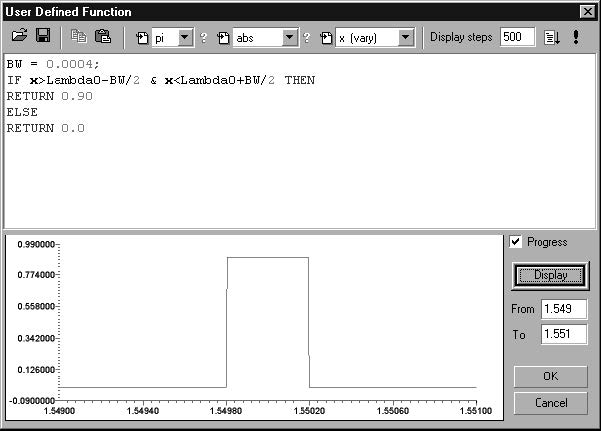
6
Set the bandwidth to 0.4 nm and the reflectivity to 0.9 within this band.
7
Click OK.
8
Select the Disp radio button and click the adjacent Define button to define the dispersion spectrum.
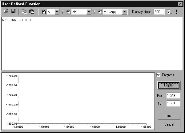
9
In this screen, set the dispersion to -1800 ps/nm for all wavelengths, as seen above.
10
Click OK.
11
Click the Causality button to see the impulse response of the specified spectrum.
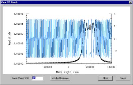
12
Click Close.
Step 2
1
Click Start in the Inverse Problem Solver dialog box to start the layer peeling algorithm..
2
Select the Delay tab.
3
Select the red and light blue curves to show the transmitted and reflected delays. The dark blue curve shows the target delay.
4
Click in the graph window and go to Tools > Group Delay
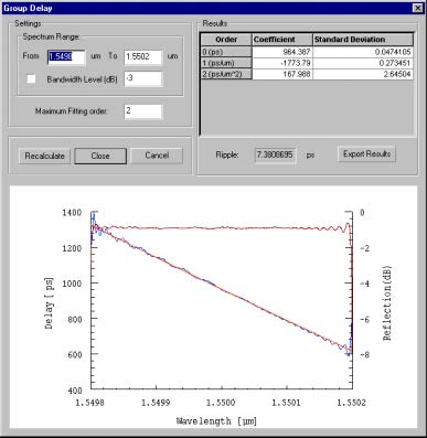
The window displays the reconstructed group delay with a second order fitting.
The dispersion is reported in the Results frame as -1773.79 ps/nm, in close
agreement with the desired response.