Optiwave software can be used in different industries and applications, including Fiber Optic Communication, Sensing, Pharma/Bio, Military & Satcom, Test & Measurement, Fundamental Research, Solar Panels, Components / Devices, etc..
OptiSystem is a comprehensive software design suite that enables users to plan, test, and simulate optical links in the transmission layer of modern optical networks.
OptiSPICE is the first circuit design software for analysis of integrated circuits including interactions of optical and electronic components. It allows for the design and simulation of opto-electronic circuits at the transistor level, from laser drivers to transimpedance amplifiers, optical interconnects and electronic equalizers.
OptiFDTD is a powerful, highly integrated, and user friendly CAD environment that enables the design and simulation of advanced passive and non-linear photonic components.
OptiBPM is a comprehensive CAD environment used for the design of complex optical waveguides. Perform guiding, coupling, switching, splitting, multiplexing, and demultiplexing of optical signals in photonic devices.
OptiFiber The optimal design of a given optical communication system depends directly on the choice of fiber parameters. OptiFiber uses numerical mode solvers and other models specialized to fibers for calculating dispersion, losses, birefringence, and PMD.
Emerging as a de facto standard over the last decade, OptiGrating has delivered powerful and user friendly design software for modeling integrated and fiber optic devices that incorporate optical gratings.
OptiConverge is a collaborative integration framework that seamlessly combines two or more Optiwave products (e.g., OptiSystem, OptiSPICE, OptiFDTD, etc.) and other third party products into unified solutions. Designed to streamline complex workflows, it empowers users to achieve their goals faster by harnessing the collective power of our trusted Optiwave tools.
Home » Tutorials » Mode Conversion by Fiber Bragg Grating
Compatibility:
Reference
C.-X. Shi and T. Okoshi, ‘Mode conversion based on the periodic coupling by a
reflective fiber grating,’ Opt. Lett., vol.17, No.23, pp.1655-1657, (1992).
Description
The example demonstrates the mode conversion between the LP01 and LP02 mode
in a fiber with Bragg grating. The fiber has four LP core modes. In the example, only
three core modes, LP01, LP02, and LP11, are selected for calculations. The grating
period, 0.21436546 microns, allows the coupling between the forward propagating
LP01 mode and the backward propagating LP02 mode.
The main results are the narrow reflection and transmission spectra showing the
conversion of selected modes.
Note: For this example, the file includes all the design data and the calculation
results.
Spectrum
The left-hand side peak is the mode conversion form LP01 mode to backward LP02. The right hand side peak is the coupling between LP01 mode to its backward mode.
Set the grating tilted angle to 3.0 degrees and click the Calculation button again.
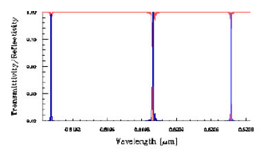
Spectrum with tilted angle of 3.0°
The peak at the middle is the mode conversion from the LP01 mode to the backward
LP11 mode.