Optiwave software can be used in different industries and applications, including Fiber Optic Communication, Sensing, Pharma/Bio, Military & Satcom, Test & Measurement, Fundamental Research, Solar Panels, Components / Devices, etc..
OptiSystem is a comprehensive software design suite that enables users to plan, test, and simulate optical links in the transmission layer of modern optical networks.
OptiSPICE is the first circuit design software for analysis of integrated circuits including interactions of optical and electronic components. It allows for the design and simulation of opto-electronic circuits at the transistor level, from laser drivers to transimpedance amplifiers, optical interconnects and electronic equalizers.
OptiFDTD is a powerful, highly integrated, and user friendly CAD environment that enables the design and simulation of advanced passive and non-linear photonic components.
OptiBPM is a comprehensive CAD environment used for the design of complex optical waveguides. Perform guiding, coupling, switching, splitting, multiplexing, and demultiplexing of optical signals in photonic devices.
OptiFiber The optimal design of a given optical communication system depends directly on the choice of fiber parameters. OptiFiber uses numerical mode solvers and other models specialized to fibers for calculating dispersion, losses, birefringence, and PMD.
Emerging as a de facto standard over the last decade, OptiGrating has delivered powerful and user friendly design software for modeling integrated and fiber optic devices that incorporate optical gratings.
OptiConverge is a collaborative integration framework that seamlessly combines two or more Optiwave products (e.g., OptiSystem, OptiSPICE, OptiFDTD, etc.) and other third party products into unified solutions. Designed to streamline complex workflows, it empowers users to achieve their goals faster by harnessing the collective power of our trusted Optiwave tools.
The “Polarization Mode Dispersion” dialog box allows you to define parameters of the
PMD model as well as choose the PMD simulation method as the ensemble
simulation or spectral simulation. Theoretically, both methods are equivalent.
To access this dialog box, do the following steps:
Step
Action
1
Select “PMD” on the Simulation menu
2
Click the “PMD” icon in the Navigator pane
Note: N.B.! The “Polarization Mode Dispersion” dialog box is accessible only after
the Birefringence calculation. If the “Birefringence” was not calculated before, its
dialog box will appear after clicking the “Polarization Mode Dispersion” dialog box.
The elements and controls of the “Polarization Mode Dispersion” dialog box options
are described below.
Birefringence Characteristics
This section provides only a display of the birefringence parameters as calculated
using the Birefringence dialog box setup.
PMD Data
The PMD Data refers to the stochastic trunks model used to calculate the Polarization
Mode Dispersion characteristics. Enter the fiber length and the coupling length
parameter.
Ensemble Simulation
With this option selected, the program performs the PMD calculations based on a
number of stochastic fibers that are generated during the simulation. You enter the
number of stochastically generated fibers.
Spectral Simulation
With this option selected, the program performs the PMD calculations using only one
stochastic fiber. However, the calculations are repeated for a number of steps within
the spectral range. You enter the spectral range and the number of steps.
See also the following sections in the Technical Background:
Polarization Mode Dispersion
Principal States of Polarization
Dispersion Vector Definition
Poincaré Sphere
Ensemble Simulation
Spectral Simulation
First Order Dispersion Definition
Second Order Dispersion Definition
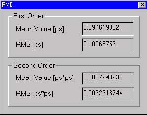
PMD dialog box
The “PMD” dialog box is only a display of the numerical values related to the
Polarization Mode Dispersion (PMD) calculation.
This dialog box appears automatically when the PMD calculations are finished and
the PMD tab is selected in the output Views window.