
Mode field diameter and area importance
The Mode Field Diameter (MFD) is an important parameter related to the optical field
distribution in the fiber. It has been shown that MFD provides useful information about
the cabling performances, such as possible joint, macrobending, and microbending
losses. The effective area of the fibers has a direct relation to the nonlinear distortions
in long fiber links. Currently OptiFiber calculates the following spatial measures of the
modes:
Near-field diameter definition
The near-field Mode Field Diameter (near-field MFD) is also known in the literature as
the “Petermann I” diameter. It is defined as the diameter at which the near field power
falls to 1 / e2 of its maximum value. It can be calculated by [Artiglia, 1989[2]:

where E(r) is the optical mode field distribution.
Far-field diameter definition
The far-field Mode Field Diameter (far-field MFD) is also known in the literature as the
“Petermann II” diameter. It is defined as the diameter at which the far field power falls
to 1 / e2 of its maximum value. It can be calculated by [Artiglia, 1989[2]]:

where E(r) is the optical mode field distribution, and prime denotes differentiation of a
function with respect to its argument.
Effective mode area definition
The effective Mode Area (eff. MA) is calculated as [see, for example, G. Agrawal,
1995]
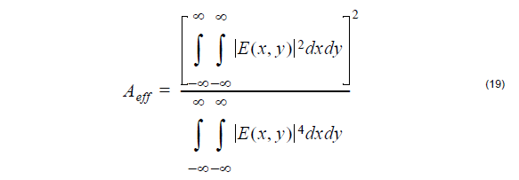
where E(x,y) is the optical mode field distribution.
Effective diameter definition
OptiFiber calculates also the effective Mode Field Diameter (eff. MFD), defined as:
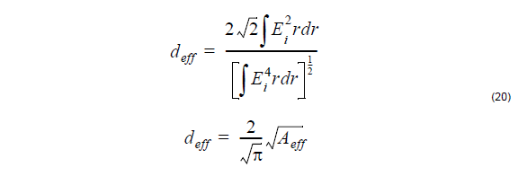
where E(r) is the optical mode field distribution.