Optiwave software can be used in different industries and applications, including Fiber Optic Communication, Sensing, Pharma/Bio, Military & Satcom, Test & Measurement, Fundamental Research, Solar Panels, Components / Devices, etc..
OptiSystem is a comprehensive software design suite that enables users to plan, test, and simulate optical links in the transmission layer of modern optical networks.
OptiSPICE is the first circuit design software for analysis of integrated circuits including interactions of optical and electronic components. It allows for the design and simulation of opto-electronic circuits at the transistor level, from laser drivers to transimpedance amplifiers, optical interconnects and electronic equalizers.
OptiFDTD is a powerful, highly integrated, and user friendly CAD environment that enables the design and simulation of advanced passive and non-linear photonic components.
OptiBPM is a comprehensive CAD environment used for the design of complex optical waveguides. Perform guiding, coupling, switching, splitting, multiplexing, and demultiplexing of optical signals in photonic devices.
OptiFiber The optimal design of a given optical communication system depends directly on the choice of fiber parameters. OptiFiber uses numerical mode solvers and other models specialized to fibers for calculating dispersion, losses, birefringence, and PMD.
Emerging as a de facto standard over the last decade, OptiGrating has delivered powerful and user friendly design software for modeling integrated and fiber optic devices that incorporate optical gratings.
OptiConverge is a collaborative integration framework that seamlessly combines two or more Optiwave products (e.g., OptiSystem, OptiSPICE, OptiFDTD, etc.) and other third party products into unified solutions. Designed to streamline complex workflows, it empowers users to achieve their goals faster by harnessing the collective power of our trusted Optiwave tools.
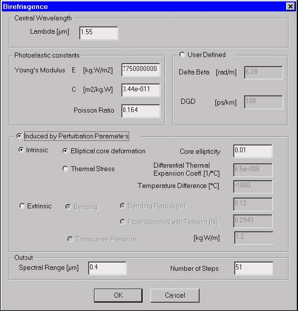
The “Birefringence” dialog box allows you to define parameters of the fiber
birefringence model. As described in the “Technical Background”, various
mechanisms contribute to fiber birefringence. You can simply define birefringence
values or follow one of the OptiFiber models.
To access this dialog box, do one of the following steps:
Step
Action
1
Select “Birefringence” on the Simulation menu
2
Click the “Birefringence” icon in the “Navigator” pane , or
3
Access it by double-clicking in the “Birefringence” view tab.
The elements and controls of the “Birefringence” dialog box options are described
below.
Central Wavelength
Enter the central wavelength for the birefringence calculations.
User Defined
To characterize the birefringence phenomena without OptiFiber models, enter the
following coefficients:
Delta Beta – Difference between the propagation constants of the two
orthogonally polarized modes
DGD – Differential Group Delay (DGD) related to fiber birefringence
Photoeleastic Constants
A group of constants characterizes photoelastic properties of the fiber: the Young
modulus, C coefficient, and Poisson ratio. This section is enabled when you intend to
use OptiFiber birefringence models.
Induced by Perturbation Parameters
This section refers to birefringence caused by intrinsic and extrinsic fiber
perturbations.
Intrinsic options:
Elliptical Core Deformation – Enter the Core Ellipticity parameter.
Thermal Stress – Enter the Differential Thermal Expansion Coefficient and Temperature Difference values.
Extrinsic options:
Bending Radius – Enter the bending radius.
Fiber Spooled with Tension – Enter the tension force value.
Transverse Pressure – Enter the transverse pressure value.
Output
The birefringence calculations are performed over a spectral range around the
Central Wavelength value. You enter the spectral range and the number of calculation
steps.
See also the following sections in the Technical Background: