Besides the typical global simulation parameters of OptiSystem, such as Bit rate, Samples per bit and Sequence length, there are two additional parameters that are very important when designing bidirectional systems or systems with closed loops, such as ring networks.
These parameters are
- Iterations
- Initial delay
Iterations force a component to calculate again until it generates, at the output ports, the Iterations number of signals.
Initial delay forces a component to generate a null signal for each output port.
Because the majority of OptiSystem components will not calculate if a signal is not available at the input ports, the Iterations and Initial delay parameter will help the user to avoid a situation in which the simulation will not perform because a component cannot find signals at the input port – and the system will be deadlocked.
The concept of multiple iterations and delays is very confusing, because it does not have a physical meaning. It is a simulation technique and requires an understanding of the calculation scheduler of OptiSystem.
A basic bidirectional simulation
System setup
- Using the default global parameters, we can start adding the components to design the basic bidirectional system.
From the component library, drag and drop the following component in to the layout:
- From “Default/Transmitters Library/Optical Sources”, drag and drop the “CW Laser” into the layout.
- Change the laser parameter Linewidth to 0 MHz.
- From “Default/Passives/Optical/Isolators”, drag and drop the “Isolator” components into the layout.
- Change the Isolator parameter Insertion loss to 3 dB.
- From “Default/Visualizers Library/Optical”, drag and drop 3 of the “Optical Spectrum Analyzer” into the layout.
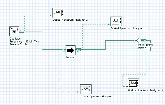
The next step is to connect the components according to the Figure 1. Do not forget to connect the Isolator Input 2 at the Output 2.
Figure 1: Basic bidirectional system
Running the simulation
We can run this simulation and analyze the results:
- To run the simulation you can go to the File menu and select Calculate. You can also press Control+F5 or use the calculate button in the toolbar. After you select Calculate, the calculation dialog box should appear.
- In the calculation dialog box, press the Play button.The calculation should perform without errors.
Viewing the results – system deadlock
In order to see the results, double click at each of the OSA visualizers.
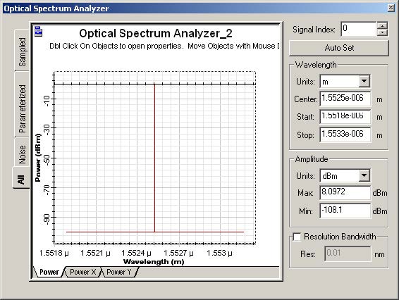
The OSA connected at the CW Laser output will have a signal as presented in Figure 2.
As expected, we have a CW signal centered at 193.1 THz with peak power around 0 dBm. However, the other two OSAs have no signals, and this is also expected.
Why is this expected? It is expected because the Isolator does not have a signal at each input port. The laser will send a signal to the first input port of the isolator. However, the isolator will not calculate if a signal is not available at the second port – the system is deadlocked.
Figure 2: CW Laser output
Using delays
What if we add a delay at the second input port of the Isolator?
- From “Default/Tool library”, drag and drop the “Optical Delay” into the layout.
- Add another OSA to the system.
- Connect the component according to Figure 3.
The delay component is important because, unlike the Isolator, it will calculate without having a signal at the input port. If the laser and the delay calculate, the Isolator will have signals available at both input ports.
Run the simulation again and open the visualizers.
Figure 3: Basic bidirectional system using a delay
Viewing the results
Let’s take a look at the signal at the second port of the Isolator. As expected, the input signal was attenuated by the isolator insertion loss and the peak power is -3 dBm. The OSA at the first isolator output shows the value of the return loss of the device and the peak power is -60 dBm.
Now, let’s see the signal at the Delay output. If we open the OSA at the delay output there is no signal – it is empty. This is the result of the first calculation of the delay. There was no input signal and the delay generated a null signal. This null signal and the laser signal were sent to the Isolator inputs. The isolator calculated with these two signals and generated a signal per output port.
One of the signals went back to the delay, which will then transfer the signal to its output port. This means there are two signals at the delay output: the null signal and the signal from the isolator.
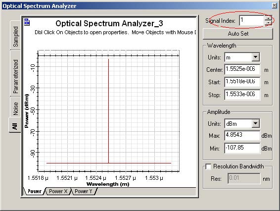
In order to browse through the signals at the delay output you should use the Signal index parameter from the OSA. Set the signal index to 1 and you will see the signal from the isolator, with peak power of -3 dBm (Figure 4).
Figure 4: Second signal at the delay output
This means we could calculate using the isolator, however the results are not exactly what we expect in this type of bidirectional system. There is a feedback between the second isolator input and output port that did not cause any effect in our results. We should force the signal to “circulate” between the laser, isolator and delay in order to see the signal evolution in the system.
In order to force the signal to circulate multiple times in the system, we can force the laser to generate the same signal multiple times, forcing the component to calculate multiple times – because there will be signals available at the input ports of the isolator and delay.
Using Iterations parameter
Change the global parameter Iterations to 10, run the simulation again.
Viewing the results
Let’s see the results from the OSAs. The laser generated 10 signals. You can change the signal index parameter at the laser output and see that the signal power does not change. This is expected, because we have 10 copies of the same signal.
We expect the second isolator output signal to have -3dBm of power. However we don’t know the power at the first isolator output port. This port will have the laser input power reflected by the return loss, plus the feedback signal attenuated by the isolator insertion loss.
Look at the OSA at the isolator outputs in order to evaluate the results. Do not forget to change the signal index!
By changing the signal index you can see how the power changes per iteration. We are using 10 iterations but 2 or 3 should be enough to give a “steady-state” value for the output power of the OSAs.
Cascading devices
Let’s make the system more complicated:
- Duplicate the Isolator.
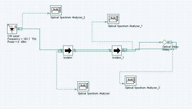
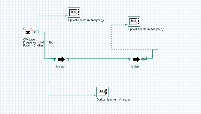
- Connect the component according to Figure 5.
From what we learned until now, it seems obvious that this system will be deadlocked because the two Isolators will not have signals at the input ports.
You can run the simulation and you will see that the 10 signals from the laser will not reach all the visualizers. In order to make the system work, we should add more delays:
- Duplicate the delay twice.
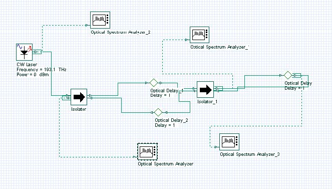
- Connect the component according to Figure 6.
If you run the simulation again, the system will run properly. You should increase the OSA signals index in order to visualize the proper results.
Figure 5: Basic bidirectional system cascading two isolators
Figure 6: Basic bidirectional system cascading two isolators and delays
Using Initial delay parameter
The main problem with cascading these devices is that the user should add delays per each input port, and this can be cumbersome for some designs. This is why OptiSystem allows the user to include a delay by default for each input port:
- Remove the delays.
- Connect the component according to Figure 7.
- In the global parameters, enable parameter Initial delay.
- Run the simulation.
This time we have a clean design, without multiple delays. The final results are the same as adding the delays.
There is one main difference between the designs of Figure 6 and 7. By enabling the global parameter initial delay, all components will generate a null signal, including the laser component. This is not true for Figure 6, in which only the delays generated the null signals.
Figure 7: Basic bidirectional system with two isolators in cascade
Tools library
OptiSystem Tools Library has components that can manipulate signals and signal buffers.
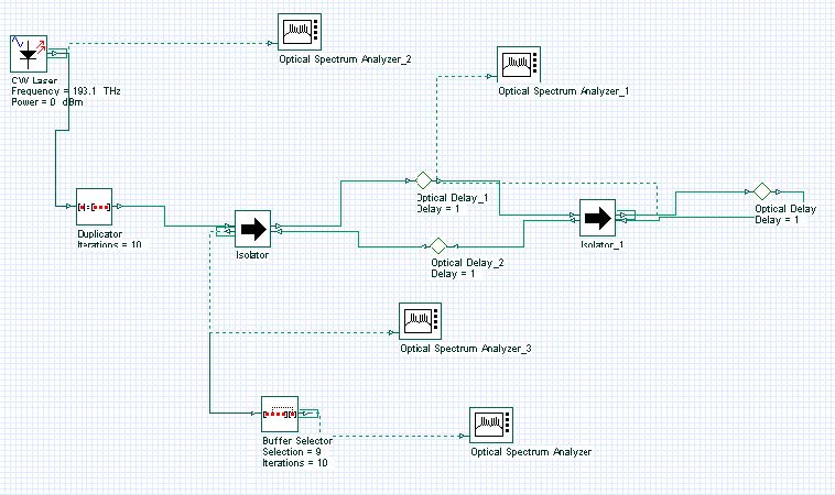
Signals can be duplicated, selected, initialized, etc. For example, Figure 8 presents a system that is equivalent to Figure 6, without using global parameters: Iterations = 1 and Initial delay = disabled.
- Repeat the steps to generate Figure 6 layout.
- Set the global iterations parameter to 1.
- Set the Initial delay parameter to disabled status.
- From “Default/Tool library”, drag and drop the “Duplicator” into the layout.
- Change the parameter Iterations mode to Normal. Set the value to 10.
- From “Default/Tool library”, drag and drop the “Buffer selector” into the layout.
- Change the parameter Iterations and Selection mode to Normal. Set the value of Iterations to 10 and Selection to 9.
- Connect the component according to Figure 8.
- Run the simulation.
Figure 8: Bidirectional system using duplicator, delay and selector
This time the duplicator component will do the job of generating multiple signals. It will generate 10 copies of the signal from the laser. The selector will select the last signal from the input buffer and sent it to the output port.
This means the signal index parameter of the OSA connected to the Selector will have only one value:0. This is because the other signals were filtered by the selector component.


