Optiwave software can be used in different industries and applications, including Fiber Optic Communication, Sensing, Pharma/Bio, Military & Satcom, Test & Measurement, Fundamental Research, Solar Panels, Components / Devices, etc..
OptiSystem is a comprehensive software design suite that enables users to plan, test, and simulate optical links in the transmission layer of modern optical networks.
OptiSPICE is the first circuit design software for analysis of integrated circuits including interactions of optical and electronic components. It allows for the design and simulation of opto-electronic circuits at the transistor level, from laser drivers to transimpedance amplifiers, optical interconnects and electronic equalizers.
OptiFDTD is a powerful, highly integrated, and user friendly CAD environment that enables the design and simulation of advanced passive and non-linear photonic components.
OptiBPM is a comprehensive CAD environment used for the design of complex optical waveguides. Perform guiding, coupling, switching, splitting, multiplexing, and demultiplexing of optical signals in photonic devices.
OptiFiber The optimal design of a given optical communication system depends directly on the choice of fiber parameters. OptiFiber uses numerical mode solvers and other models specialized to fibers for calculating dispersion, losses, birefringence, and PMD.
Emerging as a de facto standard over the last decade, OptiGrating has delivered powerful and user friendly design software for modeling integrated and fiber optic devices that incorporate optical gratings.
OptiConverge is a collaborative integration framework that seamlessly combines two or more Optiwave products (e.g., OptiSystem, OptiSPICE, OptiFDTD, etc.) and other third party products into unified solutions. Designed to streamline complex workflows, it empowers users to achieve their goals faster by harnessing the collective power of our trusted Optiwave tools.
Home » Tutorials » Power Calculation and Poynting Vector
Compatibility:
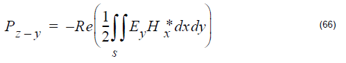
For the z-direction propagation wave. The total power in x-y plane can be divided into
two power values: x-direction polarized z-direction propagation power (Pz-x) and y-direction polarized z-direction propagation power (Pz-y). The corresponding formulas
are:
x-polarization power
y-polarixation power
Total power
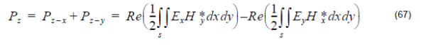
where the cap dot indicates the complex value that comes from the DFT calculation,
and the superscript star indicates the complex conjugate value.
The z-direction Poynting for a point (i,j,) in x-y plane is:
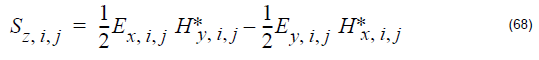
The Poynting vector is a complex value. In OptiFDTD, only the amplitudes are
displayed to the user.
Overlap Integral (OI)
Overlap Integral do the inner product and integral calculation for the two electric fields
in a specified region. The results can also be seen as the Correlation Function, or as
a comparison between the two fields. The Overlap Integral (MOI) is defined as:
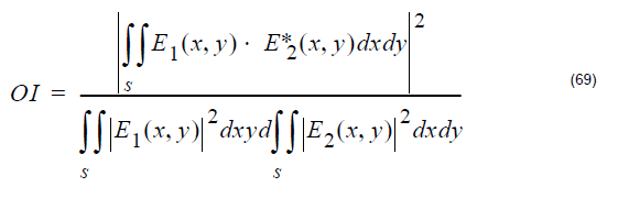
The cap dot represents the complex value, and the superscript star represents the
conjugate value, is the first field component, and is the second field
component.
Mode Overlap Integral (MOI)
For mode overlap integral calculation, the first component in Equation 69 are the
OptiFDTD simulated DFT results in a selected x-y plane, and the second components
are the modal components that come from the mode solver for the same x-y plane.
Input Overlap Integral (IOI)
For Input Overlap Integral, the first component in Equation 69 are the OptiFDTD
simulated DFT results in a selected x-y plane, and the second component is the
input wave in the input plane. The input overlap integral is also called the power overlap integral. The input overlap integral provides the criteria to do the comparison between the output in the selected plane and the input wave.
Input Overlap Integral Scan (IOIS)
The Input Overlap Integral Scan makes the Input Overlap Integral calculations for all
the x-y slices in the z-direction. This means that it scans the IOI calculation in the z-direction, and the results are provided to the user interface. Users can observe
percentages of output power in each slice.Far Field Transform.