Optiwave software can be used in different industries and applications, including Fiber Optic Communication, Sensing, Pharma/Bio, Military & Satcom, Test & Measurement, Fundamental Research, Solar Panels, Components / Devices, etc..
OptiSystem is a comprehensive software design suite that enables users to plan, test, and simulate optical links in the transmission layer of modern optical networks.
OptiSPICE is the first circuit design software for analysis of integrated circuits including interactions of optical and electronic components. It allows for the design and simulation of opto-electronic circuits at the transistor level, from laser drivers to transimpedance amplifiers, optical interconnects and electronic equalizers.
OptiFDTD is a powerful, highly integrated, and user friendly CAD environment that enables the design and simulation of advanced passive and non-linear photonic components.
OptiBPM is a comprehensive CAD environment used for the design of complex optical waveguides. Perform guiding, coupling, switching, splitting, multiplexing, and demultiplexing of optical signals in photonic devices.
OptiFiber The optimal design of a given optical communication system depends directly on the choice of fiber parameters. OptiFiber uses numerical mode solvers and other models specialized to fibers for calculating dispersion, losses, birefringence, and PMD.
Emerging as a de facto standard over the last decade, OptiGrating has delivered powerful and user friendly design software for modeling integrated and fiber optic devices that incorporate optical gratings.
OptiConverge is a collaborative integration framework that seamlessly combines two or more Optiwave products (e.g., OptiSystem, OptiSPICE, OptiFDTD, etc.) and other third party products into unified solutions. Designed to streamline complex workflows, it empowers users to achieve their goals faster by harnessing the collective power of our trusted Optiwave tools.
The basic FDTD algorithm must be modified at the boundaries of the computational
window where suitable numerical absorbing boundary conditions (ABC) are applied.
This is one of the most challenging parts of FDTD simulations. There are several
choices for the type of boundary conditions. The Perfectly Matched Layer (PML)
boundary conditions have the best performance. Our FDTD simulator uses the
Anisotropic PML, or so-called Un-split PML (UPML) version. The theory of the UPML
is very well explained in some of the references given here. The UPML boundary
conditions are physical rather than numerical because their implementation is based
on a Maxwellian formulation rather than on a mathematical model. Their absorbing
properties are physically equivalent to the properties of an absorbing uni-axial
anisotropic medium with the following permittivity and permeability tensors:
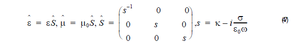
A plane wave incident on a half space composed of the above uniaxial medium with
an interface in the x = const plane is purely transmitted into it. The reflectionless
property is completely independent of the angle of incidence, polarization and
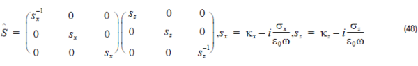
frequency of the incident wave. The numerical implementation of the UPML in a 2D
(X-Z) computational window requires the introduction of such perfectly matched
absorbing layers on all the sides. The corner regions need special attention. In these
regions the tensor from Equation 47 must be modified to:
The minimization of the numerical reflectance of the Anisotropic PML layers requires
spatial scaling of the conductivity profile from zero (at the interface of the PML) to a
maximum value at the end of the computational window:
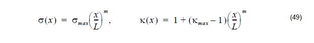
where L is the thickness of the Anisotropic PML. Typical values for the parameter m
are between 2 and 4.