Optiwave software can be used in different industries and applications, including Fiber Optic Communication, Sensing, Pharma/Bio, Military & Satcom, Test & Measurement, Fundamental Research, Solar Panels, Components / Devices, etc..
OptiSystem is a comprehensive software design suite that enables users to plan, test, and simulate optical links in the transmission layer of modern optical networks.
OptiSPICE is the first circuit design software for analysis of integrated circuits including interactions of optical and electronic components. It allows for the design and simulation of opto-electronic circuits at the transistor level, from laser drivers to transimpedance amplifiers, optical interconnects and electronic equalizers.
OptiFDTD is a powerful, highly integrated, and user friendly CAD environment that enables the design and simulation of advanced passive and non-linear photonic components.
OptiBPM is a comprehensive CAD environment used for the design of complex optical waveguides. Perform guiding, coupling, switching, splitting, multiplexing, and demultiplexing of optical signals in photonic devices.
OptiFiber The optimal design of a given optical communication system depends directly on the choice of fiber parameters. OptiFiber uses numerical mode solvers and other models specialized to fibers for calculating dispersion, losses, birefringence, and PMD.
Emerging as a de facto standard over the last decade, OptiGrating has delivered powerful and user friendly design software for modeling integrated and fiber optic devices that incorporate optical gratings.
OptiConverge is a collaborative integration framework that seamlessly combines two or more Optiwave products (e.g., OptiSystem, OptiSPICE, OptiFDTD, etc.) and other third party products into unified solutions. Designed to streamline complex workflows, it empowers users to achieve their goals faster by harnessing the collective power of our trusted Optiwave tools.
Home » Tutorials » Parameter Sweep Simulation Introduction
Compatibility:
There are two ways to perform the parameter sweep simulation with OptiFDTD:
• Simulation Using Script. This method asks the user to edit the VBscript code to sweep the layout parameters. The user can use the internal VB function to access the power spectrum.
• Simulation Using automated Sweep. With this method, OptiFDTD provides a graphical user interface to define the swept parameters, iterations and a parameter sweep viewer to observe all the results (power in the center wavelength, transmission spectrum and reflection spectrum) for all the swept parameters.
Simulation Using Sweep mode can be transformed to Simulation Using Script mode, i.e. a VB script code can be automatically generated after the sweep parameters are defined in the parameter sweep interface. For users who want to use these VB functions, please check the corresponding reference and the automatically generated VB code.
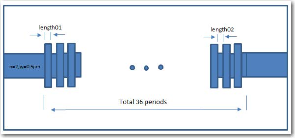
In this lesson, we will discuss how to use Simulation Using Sweep and the corresponding results viewer. A simple 2D grating layout will be used to demonstrate the steps. Figure 1 is a layout sketch. The layout contains input/output waveguides and 36-period grating. Both waveguides use the same material with a refractive index of n=3.3. Each grating unit cell contains two waveguides: the first has a width of 0.7µm and a variable length of “length01”, the width of the second waveguide is 0.5 µm with a variable length of “length02”. We will try to scan the two parameters “length01” and “length02” in the simulation. The sample layout can be found in the 64bit sample folder, titled “x64_sample63_2DTM_2LevelParamterSweep.fdt”. folder, titled “x64_sample63_2DTM_2LevelParamterSweep.fdt”.