
Fraunhofer approximation
Narrow angle far-field transform being used in OptiFDTD is based on the Fraunhofer
approximation:

At a large distance d, the far field position can be expressed by the far field angle,
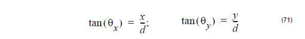
Where the x-directional angle (θx) is the angle between the original yz-plane and the
shortest straight line connecting the point and the Y axis, and y-directional angle
(θy) is the angle between the original xz-plane and the shortest straight line
connecting the point and the x axis. The far field angle is also shown in the Figure 22.
Associated with the angle where to observe the far-field, far-field formula now can be
simplified as
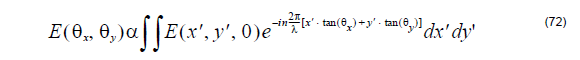
Please note that the above formula assumes that the far-field plane is far away from
the near field one. OptiFDTD uses Equation 72 to calculate the narrow angle far field
transform.
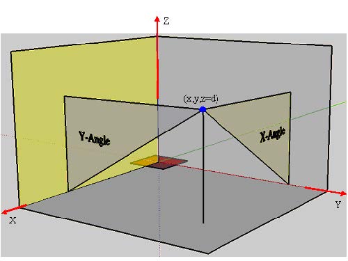
Figure 22 Far-field angle (the red region is the near field)
Fresnel-Kirchhoff Diffraction Formula
Wide angle far field transform is based on the Fresnel-Kirchhoff diffraction formula [1].
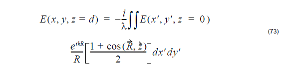
Where R is the vector from near-field to far-field.
The far-field position can be expressed with far field angle the far-field distance z=d.
So in the wide angle far field transform, the user needs to specify the far-field distance.
Heating Absorption
It is known that the real electromagnetic power transmitted through the closed surface
S into the volume V is equal to the power loss produced by conduction current
resulting in Joule heating plus the power loss resulting from polarization damping
forces.
From the complex Poynting vector theorem, the time-average heating absorption
intensity is expressed as

where σ is the conductivity that may be varied with wavelength, E is the electrical field
components.
In OptiFDTD, for each cell in a given observation area, the heating absorption
intensity for each polarization then can be expressed as

where the subscript letter, x,y and z means the polarization direction, i and j is the
position index.
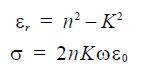
Then the total heating absorption for one observation slice will be the integral of the
heating absorption intensity in the volume
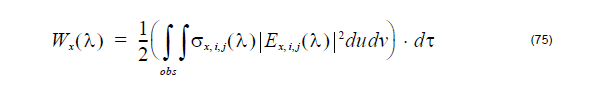
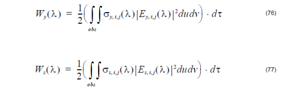
Where du and dv are the mesh size in the observation plane, dτ is the third
dimensional (vertical to the observation area) space step. The total heating
absorption in the whole observation slice will be

Heating absorption calculation needs the conductivity. Basic formula between
permittivity and refractive index is

So the permittivity and conductivity is
For Lorentz_Drude model material
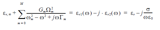
The conductivity can be delivered as
![]()