Based on the information found in the Technical Background, the extraordinary
refractive index, ne , of Ti:Lithium Niobate diffused waveguide have the following
profile:

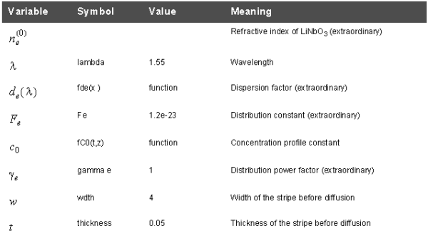
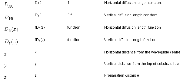
The symbols, variables, and functions are explained in Table 9, Table 10, and in the
Technical Background.
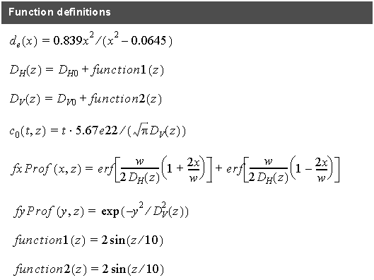
As the equation for refractive index is exceedingly long, we rewrite the equation with the help of auxiliary functions fxProf and fyProf in a form suitable for
implementation:
All the definitions of auxiliary functions can be found in Table 10.
Note: The z-dependencies of the vertical and horizontal diffusion constants are defined by function1 and function2, which were chosen arbitrarily to be the sin functions of the z-position.


Table 9: Functions and Variables

Table 10: Function Definitions
User Variables and Functions
Once you have the expression for refractive index in a suitable form, start defining all the variables identified within the equation (Table 9).
Defining variables
| Step | Action |
| 1 | In the Layout Designer, from the Simulation menu, select Edit Parameters.
The Variables and Functions dialog box appears. |
| 2 | Click the User Variables tab. |
| 3 | For example, to define a variable thickness, type the following:Name: thickness
Expression: 0.05 |
| 4 | Click Verify. |
| 5 | Click Add/Apply.
The thickness variable appears in the User Variable table. |
Defining functions
With all the variables defined, continue with defining functions in Table 10. This order is
necessary since the variables are used within the functions. If not defined, you will get an error trying to use them in other functions definitions. For a list of internally predefined constants and functions ( π, e, … ), which can be used, see Appendix D: Parser supported functions.
To define a function, perform the following procedure.
| Step | Action |
| 1 | In the Layout Designer, from the Simulation menu, select Edit Parameters.The Variables and Functions dialog box appears. |
| 2 | Click the User Functions/DLLs tab. |
| 3 | For example, to define fDx(z), type the following:Function specification: fDx(z)Expression: Dx0+2*sin(z/10) |
| 4 | Click Verify. |
| 5 | Click Add/Apply.The fDx(z) variable appears in the User Function table. |
Defining the user defined profile
By now, all the variables and auxiliary functions necessary for the profile are prepared. Proceed creating the user defined profile as follows:
| Step | Action | ||||||||||||
| 1 | In the Profile Designer, right-click the Profiles folder, select User Function Profile, and select New. | ||||||||||||
| 2 | Type the Profile name: TiUsrProf_Dv_exordinary. | ||||||||||||
| 3 | Select Function is additive.Note: When the function is additive, the value of the defined function is automatically added to the refractive index of the substrate. Using this option we have addressed the first term in the equation, ne( 0 ) . You must ensure that you select the orientation of the substrate material, propagation direction, and polarization so that the extraordinary index is actually used in the simulation. An alternative approach would be to define the constant ne( 0 ) and to use it in the non- additive profile definition (non-additive profiles overwrite the substrate refractive index). | ||||||||||||
| 4 | Type/enter the following:a. Function specification: dn_e(x,y,z)
Note: The specification defines the name of the function and number of input parameters. In this case, we need three position parameters (x,y,z). b. Function body: fde(lambda)*fC0(thickness,z)*Fe*fxProf(x,z)*fyProf(y,z) c. Material: LithiumNiobate_1 |
||||||||||||
| 5 | Click the Profile function tab. | ||||||||||||
| 6 | Click in the Association cells and make the following selections from the drop-down list (see ):
|
||||||||||||
| 7 | Click Verify. | ||||||||||||
| 8 | Click Store. | ||||||||||||
| 9 | Close the Profile Designer.Now we can check the profile of the newly created user defined profile against a predefined Ti:LiNbO3 diffused profile. |
Checking the user defined profile against the reference profile
| Step | Action |
| 1 | Create a new Diffusion-Ti:LiNbO3 profile with the same parameters. |
| 2 | In the Waveguide Layout Designer, define two straight linear waveguides in the layout:Waveguide 1
Start: Horizontal Offset: 0 Vertical Offset: –6 End: Horizontal Offset: 100 Vertical Offset: –6 Width: wdth Profile: TiUsrProf_Dv_exordinary Waveguide 2 Start: Horizontal Offset: 0 Vertical Offset: 6 End: Horizontal Offset: 100 Vertical Offset: 6 Width: wdth Profile: Ti:LiNbO3 |
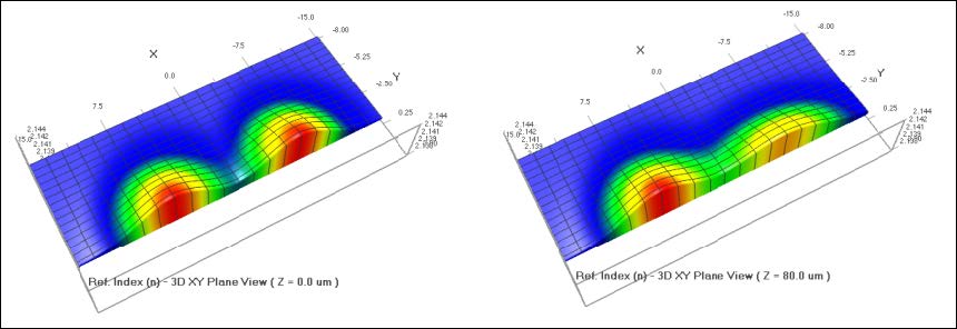
In the 3D refractive index view, you can check that the two profiles are the same for z = 0, due to the fact that the Diffusion length at z=0 is equal to the predefined variables Dx0 and Dy0. If you view the refractive index at different positions, you will see differences. The predefined waveguide does not change its profile along the z-coordinates, whereas the user defined waveguide has non-constant diffusion lengths which are functions of z-coordinates (see Table 10).
 Figure 16: Refractive index profiles at z=0 (picture at left) and z=80 (picture at right). The predefined diffused waveguide,on the left of each picture, does not change. The user defined waveguide (the right profile in each picture) depends on the z-coordinate as expected.
In this lesson, we added an additional feature compared to the predefined diffusion profiles – we allowed the horizontal and vertical diffusion lengths to be functions of the z -coordinate (note the sinusoidal modulation of the fDy(z) and fDx(z).
Both profiles can be used in 2D and 3D simulations. Compared to the predefined diffusion profiles (Ti:LiNbO3, Mg:LiNbO3, PE:LiNbO3) there will be no effective index calculation to get 2D refractive index distribution. Instead, when using the user defined diffusion profiles, the 2D refractive index distribution will be defined by the slice of 3D refractive index at the top of the substrate, i.e. y=0.0.
Also note that the user function profiles can only be defined within the substrate. If your function is not already limited within the substrate by using the limits, it will simply be ignored within the cladding region.
The variable lambda should be input into the wavelength input field within the simulation parameters so that the chromatic dispersion factor is obtained for the correct wavelength.
Finally, the simulation will run slower than a normal predefined diffused waveguide due to the fact the refractive index formula needs to be ‘translated’ and calculated in every slice (z-dependence of the Dv and Dh).

