Optiwave software can be used in different industries and applications, including Fiber Optic Communication, Sensing, Pharma/Bio, Military & Satcom, Test & Measurement, Fundamental Research, Solar Panels, Components / Devices, etc..
OptiSystem is a comprehensive software design suite that enables users to plan, test, and simulate optical links in the transmission layer of modern optical networks.
OptiSPICE is the first circuit design software for analysis of integrated circuits including interactions of optical and electronic components. It allows for the design and simulation of opto-electronic circuits at the transistor level, from laser drivers to transimpedance amplifiers, optical interconnects and electronic equalizers.
OptiFDTD is a powerful, highly integrated, and user friendly CAD environment that enables the design and simulation of advanced passive and non-linear photonic components.
OptiBPM is a comprehensive CAD environment used for the design of complex optical waveguides. Perform guiding, coupling, switching, splitting, multiplexing, and demultiplexing of optical signals in photonic devices.
OptiFiber The optimal design of a given optical communication system depends directly on the choice of fiber parameters. OptiFiber uses numerical mode solvers and other models specialized to fibers for calculating dispersion, losses, birefringence, and PMD.
Emerging as a de facto standard over the last decade, OptiGrating has delivered powerful and user friendly design software for modeling integrated and fiber optic devices that incorporate optical gratings.
OptiConverge is a collaborative integration framework that seamlessly combines two or more Optiwave products (e.g., OptiSystem, OptiSPICE, OptiFDTD, etc.) and other third party products into unified solutions. Designed to streamline complex workflows, it empowers users to achieve their goals faster by harnessing the collective power of our trusted Optiwave tools.
When the output waveguides are tilted, the phase becomes a sloped straight line. In You must be careful which point you use to calculate θwg. You must know exactly which point was used to make the information consistent with definitions used in the OptiSystem calculation.
Figure 32 illustrates a tilted waveguide. The BPM zone is connected to an external waveguide outside. The other waveguide is characterized by another separate BPM calculation, or (in the case of a straight isolated waveguide) by a user-supplied manual calculation. The length of the external waveguide depends on the reference point used in the definition. The reference point is the place where the optical phase is taken from.
Figure 32: Define the length of the waveguide outside the BPM zone
It doesn’t matter which of the three possible lengths shown is used, provided that the length definition and the optical phase point are taken from the same place.
To avoid confusion, we recommend the following rules, broken down case by case.
2D Calculation
For 2D calculations, use the mesh point closest to the centre of the waveguide where it intersects the end of the calculation.
3D Channel
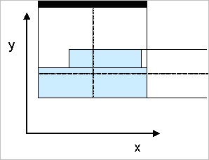
For the 3D Channel waveguide, the view from the layout in the x-z plane defines the width of the entire channel. Use the midpoint of the channel in the x-z plane to define the x coordinate of the optical phase point. This makes the definition consistent with the 2D definition (see Figure 33).
Figure 33: Midpoints for 3D Channel
The channel consists of layers at a certain depth. Use the midpoints at the top of the uppermost layer and the bottom of the lowest layer to define the y coordinate of the optical phase point.
3D Fiber
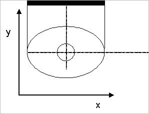
The 3D fiber consists of concentric circular or elliptic layers. Use the common center point of the layers (see Figure 34).
Figure 34: Midpoint for fiber
3D Diffused
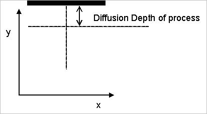
The midpoint in x can be defined the same way as for the other midpoints. A good nominal distance to move below the substrate is the diffusion length for the diffused waveguide under consideration (see Figure 35).