Optiwave software can be used in different industries and applications, including Fiber Optic Communication, Sensing, Pharma/Bio, Military & Satcom, Test & Measurement, Fundamental Research, Solar Panels, Components / Devices, etc..
OptiSystem is a comprehensive software design suite that enables users to plan, test, and simulate optical links in the transmission layer of modern optical networks.
OptiSPICE is the first circuit design software for analysis of integrated circuits including interactions of optical and electronic components. It allows for the design and simulation of opto-electronic circuits at the transistor level, from laser drivers to transimpedance amplifiers, optical interconnects and electronic equalizers.
OptiFDTD is a powerful, highly integrated, and user friendly CAD environment that enables the design and simulation of advanced passive and non-linear photonic components.
OptiBPM is a comprehensive CAD environment used for the design of complex optical waveguides. Perform guiding, coupling, switching, splitting, multiplexing, and demultiplexing of optical signals in photonic devices.
OptiFiber The optimal design of a given optical communication system depends directly on the choice of fiber parameters. OptiFiber uses numerical mode solvers and other models specialized to fibers for calculating dispersion, losses, birefringence, and PMD.
Emerging as a de facto standard over the last decade, OptiGrating has delivered powerful and user friendly design software for modeling integrated and fiber optic devices that incorporate optical gratings.
OptiConverge is a collaborative integration framework that seamlessly combines two or more Optiwave products (e.g., OptiSystem, OptiSPICE, OptiFDTD, etc.) and other third party products into unified solutions. Designed to streamline complex workflows, it empowers users to achieve their goals faster by harnessing the collective power of our trusted Optiwave tools.
The potentials themselves are solutions of the scalar Helmholtz equation, and the particular solution is found by observing the boundary conditions imposed by physical considerations on E and h. The potentials are supposed to form modes, so a solution where the variables are separated is appropriate
and a similar expression applies for the other Debye potential, ϕ . The Helmholtz equation (8) is expanded in cylindrical co-ordinates, and then (15) is substituted.For regions where ε is constant, the radial functions follow the Ordinary or Modified Bessel equation, and so the solutions are linear combinations of Bessel functions of integer order v. In any given layer,
where . In layers where the propagation constant squared is larger than k2ε , the Bessel functions J and Y are replaced by the Modified Bessel functions I and K, respectively.,
where . Equations (15), (16), and (17) are substituted in (6) and (7) to find the electromagnetic fields. It is the tangential components θ and z that are needed explicitly, since it is the tangential components of the electric and magnetic fields that should match at layer boundaries. These field components are related to the coefficients A, B, C, and D by a 4×4 matrix.
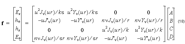
where n = β ⁄ k is the modal index, and the common factor exp [ j( νθ – βz ) ] is suppressed. In layers where the propagation constant squared is larger than k2ε , the Bessel functions J and Y are replaced by the Modified Bessel functions I and K, respectively, and the u is replaced by w.
A similar equation to (18) applies in adjacent layers, with different constants A, B, C, D. Given the constants in one layer, the constants in the adjacent layer can be found by solving the linear system created by the field matching condition. The f found by the two matrices should be the same field vector at the boundary between layers. The difference between this formulation and that in Ref. [2] and [3] is that this formulation uses real numbers only.