Optiwave software can be used in different industries and applications, including Fiber Optic Communication, Sensing, Pharma/Bio, Military & Satcom, Test & Measurement, Fundamental Research, Solar Panels, Components / Devices, etc..
OptiSystem is a comprehensive software design suite that enables users to plan, test, and simulate optical links in the transmission layer of modern optical networks.
OptiSPICE is the first circuit design software for analysis of integrated circuits including interactions of optical and electronic components. It allows for the design and simulation of opto-electronic circuits at the transistor level, from laser drivers to transimpedance amplifiers, optical interconnects and electronic equalizers.
OptiFDTD is a powerful, highly integrated, and user friendly CAD environment that enables the design and simulation of advanced passive and non-linear photonic components.
OptiBPM is a comprehensive CAD environment used for the design of complex optical waveguides. Perform guiding, coupling, switching, splitting, multiplexing, and demultiplexing of optical signals in photonic devices.
OptiFiber The optimal design of a given optical communication system depends directly on the choice of fiber parameters. OptiFiber uses numerical mode solvers and other models specialized to fibers for calculating dispersion, losses, birefringence, and PMD.
Emerging as a de facto standard over the last decade, OptiGrating has delivered powerful and user friendly design software for modeling integrated and fiber optic devices that incorporate optical gratings.
OptiConverge is a collaborative integration framework that seamlessly combines two or more Optiwave products (e.g., OptiSystem, OptiSPICE, OptiFDTD, etc.) and other third party products into unified solutions. Designed to streamline complex workflows, it empowers users to achieve their goals faster by harnessing the collective power of our trusted Optiwave tools.
In the absence of electrode fields the refractive index ellipsoid, or indicatrix, is of the following form:
where no , neare the ordinary and extraordinary refractive indices, respectively.
Under the influence of an electric field the index ellipsoid is deformed in space:
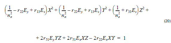
In different cases of the cut, the propagation and polarization, and the electrode field direction, different electrooptic coefficients rijare used in the simulation program. Table 4 is the reference table to help you in entering your electrooptic coefficients. The mixed coupling terms in the index ellipsoid were ignored. The change in the corresponding refractive index can be approximated as
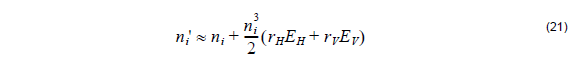
where EH , EV , rH, and rVare the electric fields in horizontal and vertical directions and the corresponding electro optic coefficients, respectively, and i denotes either ordinary or extraordinary refractive index. Notice that whether the electrode field is considered horizontal or vertical depends on the electrode configuration, voltage and the waveguide position. Intuitively, you can assume that the electrostatic field lines between electrodes follow patterns familiar from electrostatics. For example, if you place one of the electrodes right on the top of the waveguide, it will likely produce the static field that is vertical in the waveguide.