Optiwave software can be used in different industries and applications, including Fiber Optic Communication, Sensing, Pharma/Bio, Military & Satcom, Test & Measurement, Fundamental Research, Solar Panels, Components / Devices, etc..
OptiSystem is a comprehensive software design suite that enables users to plan, test, and simulate optical links in the transmission layer of modern optical networks.
OptiSPICE is the first circuit design software for analysis of integrated circuits including interactions of optical and electronic components. It allows for the design and simulation of opto-electronic circuits at the transistor level, from laser drivers to transimpedance amplifiers, optical interconnects and electronic equalizers.
OptiFDTD is a powerful, highly integrated, and user friendly CAD environment that enables the design and simulation of advanced passive and non-linear photonic components.
OptiBPM is a comprehensive CAD environment used for the design of complex optical waveguides. Perform guiding, coupling, switching, splitting, multiplexing, and demultiplexing of optical signals in photonic devices.
OptiFiber The optimal design of a given optical communication system depends directly on the choice of fiber parameters. OptiFiber uses numerical mode solvers and other models specialized to fibers for calculating dispersion, losses, birefringence, and PMD.
Emerging as a de facto standard over the last decade, OptiGrating has delivered powerful and user friendly design software for modeling integrated and fiber optic devices that incorporate optical gratings.
OptiConverge is a collaborative integration framework that seamlessly combines two or more Optiwave products (e.g., OptiSystem, OptiSPICE, OptiFDTD, etc.) and other third party products into unified solutions. Designed to streamline complex workflows, it empowers users to achieve their goals faster by harnessing the collective power of our trusted Optiwave tools.
Home » Tutorials » Conformal Mapping Regions Introduction
Compatibility:
Conformal mapping region in BPM is used to simulate curved optical waveguides. The method uses conformal mapping in the complex plane to transform a curved waveguide in ( x, y ) coordinates into a straight waveguide with a modified refractive index in new ( u, v ) coordinates (Figure 1). It can be used to treat losses in curved waveguides with both abruptly and a continuously varying refractive index, such as diffused waveguides, and the radii of curvature need not to be restricted to large values as in the first order approximations [2].
Figure 1: Conformal mapping transforms a curved waveguide in (x,y) into a straight waveguide with modified refractive index in (u,v)
Conformal mapping is an angle-preserving transformation in a complex plane. For example, consider solutions of the 2-dimensional scalar wave equation:
The solutions of the equation are found in a coordinate system ( u, v ) defined with respect to ( x, z ) by the relation
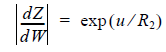
where f is an analytical function in the complex plane. In the case of curved waveguides with a bend radius of R , the following function will straighten the bent waveguide in the (u,v) plane as shown in Figure 1:
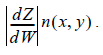
The transformation in Equation 3 leads to a new scalar wave equation:
where the Jacobian of the transformation is found to use the command:
Trying to solve the original wave Equation 1 for bends may lead to large errors due to the paraxial approximation used in BPM. Using conformal mapping technique we can avoid the limitations imposed by the paraxial approximation and simply solve the wave equation Equation 4 for a straight waveguide with a modified refractive index
Along with the argument in [3], the method can be also used in 3D cases by applying the transformation to any given depth of the waveguide.