Optiwave software can be used in different industries and applications, including Fiber Optic Communication, Sensing, Pharma/Bio, Military & Satcom, Test & Measurement, Fundamental Research, Solar Panels, Components / Devices, etc..
OptiSystem is a comprehensive software design suite that enables users to plan, test, and simulate optical links in the transmission layer of modern optical networks.
OptiSPICE is the first circuit design software for analysis of integrated circuits including interactions of optical and electronic components. It allows for the design and simulation of opto-electronic circuits at the transistor level, from laser drivers to transimpedance amplifiers, optical interconnects and electronic equalizers.
OptiFDTD is a powerful, highly integrated, and user friendly CAD environment that enables the design and simulation of advanced passive and non-linear photonic components.
OptiBPM is a comprehensive CAD environment used for the design of complex optical waveguides. Perform guiding, coupling, switching, splitting, multiplexing, and demultiplexing of optical signals in photonic devices.
OptiFiber The optimal design of a given optical communication system depends directly on the choice of fiber parameters. OptiFiber uses numerical mode solvers and other models specialized to fibers for calculating dispersion, losses, birefringence, and PMD.
Emerging as a de facto standard over the last decade, OptiGrating has delivered powerful and user friendly design software for modeling integrated and fiber optic devices that incorporate optical gratings.
OptiConverge is a collaborative integration framework that seamlessly combines two or more Optiwave products (e.g., OptiSystem, OptiSPICE, OptiFDTD, etc.) and other third party products into unified solutions. Designed to streamline complex workflows, it empowers users to achieve their goals faster by harnessing the collective power of our trusted Optiwave tools.
Home » Blog » Nano-Lens and Micro-Lens Simulations
Compatibility:
When optical lens size is compatible with the working wavelength, the traditional lens analysis tools such as ray-tracing method will lose their accuracy. The FDTD method can be used to advantage in the nano-lens simulation. OptiFDTD software also provides tools so that beam focus size, focus distance, and far-field transform can be obtained directly. The following two samples show nano-lens simulations.
SMF28 fiber lens simulation
Layout Introduction
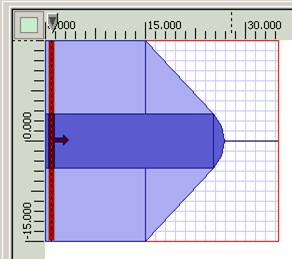
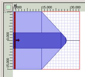
When fiber is tapered and polished in the termination as shown in Figure 1, a fiber lens can be created. The lens size can be exactly fiber’s core size or smaller than the core. In fact OptiFDTD can scan the lens size so that focus beam size and focus distance can be optimized.
Related layout can be found in OptiFDTD sample folder with project name “Sample22_VBscript_2D_Lens.FDT”
Simulation results
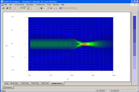
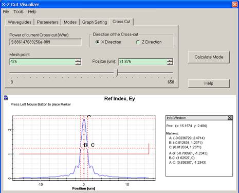
After the simulation, the field pattern and the Poynting vector can be plotted for each lens size (see figure 2), based on the field pattern, the beam size and the focus distance can be measured by the slice viewer (see figure 3)
Figure 2: Poynting vector for Fiber lens
Figure 3: Beam size measurement in OptiFDTD
Nano Lens Array
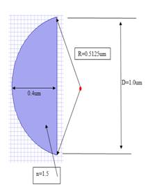
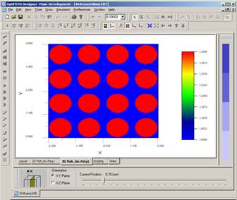
In this 3D sample, we discuss a micro-lens array, the lens dimension is marked in Figure 1, and Figure 2 is xy plane refractive index distribution.
Figure 1: Lens size
Figure 2: Top view of the lens Array
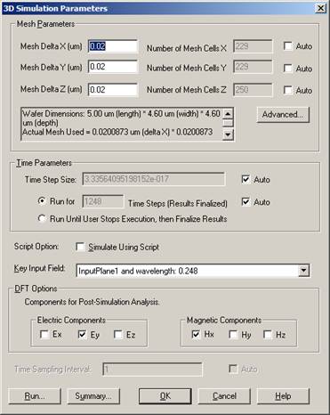
Simulation Parameters
• Mesh size : 0.02um*0.02um*0.02um
• Run for 1248 time step +
• 10 additional cycle to get the steady state field
• Calculate steady state field for Ey and Hx (Discretized Fourier transform)
• x-y boundary use the upper-lower symmetric boundary condition. Z-direction user the APML as the boundary condition
Figure 3: Simulation parameters
Simulation results
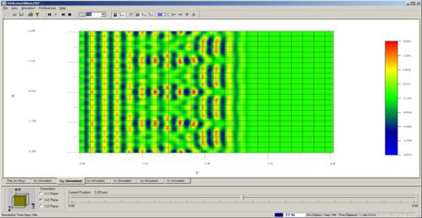
As shown in figure 4, in the simulation we can observe the time domain response in each slice in three orientations ( xy plane, yz plane, xz plane)
Figure 4: Time domain response in xz plane
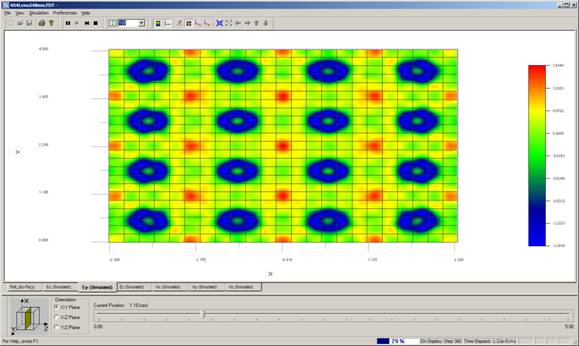
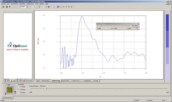
Steady state response can be observed in analyzer as shown figure 5. Beam size and focus distance can be measured in OptiFDTD as shown in figure 6
Figure 5: Field pattern in xy plane
Figure 6: Field pattern in xz plane
The calculation shows that each lens focuses at z=1.26, focus distance 1.26-0.8=0.46um