The Calculation menu allows you to do your calculations quickly and efficiently.
Run
To perform your Calculation, Spectrum, and Pulse Response calculations, just click
either Run from the Calculation menu or the Run button on the Toolbar.
In the dialog box that opens, you can see when the calculation is completed.
Scan
To perform your parameter scan calculation.
Inverse Scattering Solver
To solve the inverse scattering problem of Bragg gratings. The method is based on a layerpeeling algorithm. See the Technical Background chapter of the OptiGrating manual for details.
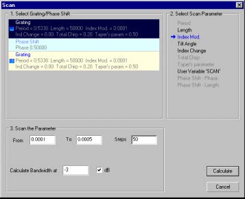
The Scan dialog box
Select Grating/Phase Shift
Select either Grating or Phase Shift from the list
Select Scan Parameter
Select a scan parameter from the grating list in this section
Scan the Parameter
From – Initial value of the scan parameter
To – final value of the scan parameter
Steps – Number of the calculation steps in the Scan calculation
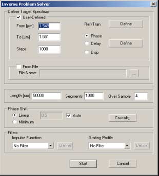
The Inverse Scattering Solver
For detailed information on how to use the Inverse Scattering Solver to solve the
inverse scattering problem, please refer to Lessons 5 -8 in the Tutorial section of the
OptiGrating manual.
From
The starting wavelength.
To
The ending wavelength.
Steps
The Steps field indicates the number of divisions used in the specified wavelength
range.
Ref/Tran Define
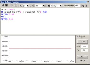
Brings up a dialog box for defining the target reflectivity spectrum as seen below:
- Click on Display to plot the curve shown. The desired impulse response will be
calculated from the Fourier transform of the reflection coefficient.
Dispersion profile Define
Located beside the Phase, Delay, and Disp radio buttons. Defines the target spectrum for the quantity indicated by the radio buttons.
Length
This is the length of the grating.
From File
Enable this checkbox and define a path to a file which contains a complex reflection
spectrum. The algorithm will try to find a grating that has this spectrum.
Segments
The grating length is divided into this number of segments. Each segment has a
constant coupling coeffiecient
Over Sample
Over Sample is used in the reconstruction ofthe truncated impulse response.
Accuracy is sometimes improved by using finer steps in the spectrum.
Causality
Clicking on this button will display the impulse response calculated from the spectrum
the user has defined.
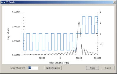
Clicking on Causality will show the following screen:
- Because of causality, any real impulse response must be zero for negative
arguements.
Note: You can experiment with various delays by entering other numbers in the
Linear Phase Shift field, and clicking the Impulse Response to see the result.
Start
Clicking on start begins the reconstruction. A progress bar indicates the progress of
the layer peeling algorithm. When this process finishes, the reconstructed grating
profile is used to generate the spectrum of the new grating. A second progress bar
displays the progress of the calculation of the spectrum


