
“Zoom X”, “Zoom XY” and “Zoom Off” are convenient tools for expanding a portion of
the graph.
“Zoom X” expands the view only in horizontal direction, “Zoom XY” – in both.
Do the following steps:
| Step | Action |
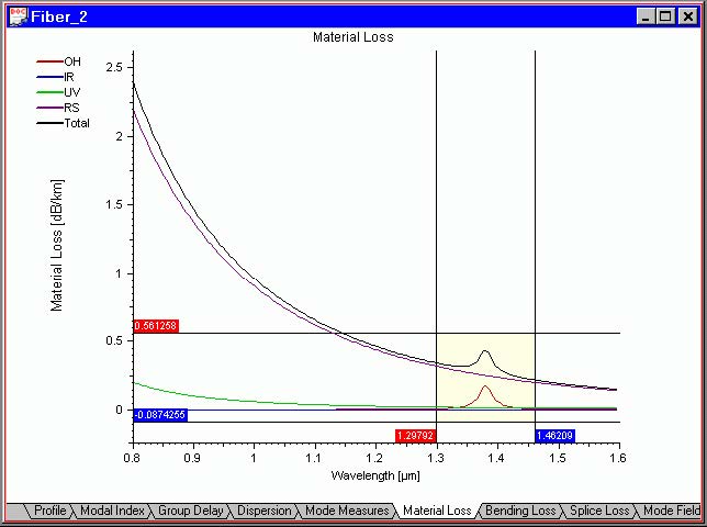
| 1 | Select, for example, the “Material Loss” tab in the Views window. |
| 2 | Select “Zoom XY” from the “Graph Tools” floating menu or the “Graph Tools” toolbar. |
| 3 | Now, with the left mouse button, click-and-drag a region to be expanded to a full graph. Before releasing the left mouse button, the View tab should look like this: |
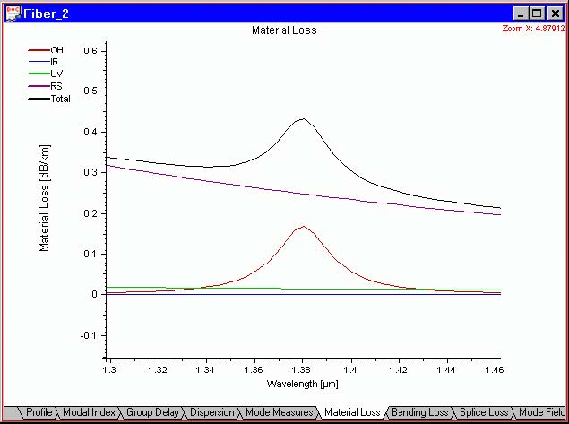
| 4 | Release the left mouse button. The selected part is expanded to the full tab. The “View” tab should now look something like this: |
| 5 | Select “Zoom Off “ to restore the default view scale. |