Optiwave software can be used in different industries and applications, including Fiber Optic Communication, Sensing, Pharma/Bio, Military & Satcom, Test & Measurement, Fundamental Research, Solar Panels, Components / Devices, etc..
OptiSystem is a comprehensive software design suite that enables users to plan, test, and simulate optical links in the transmission layer of modern optical networks.
OptiSPICE is the first circuit design software for analysis of integrated circuits including interactions of optical and electronic components. It allows for the design and simulation of opto-electronic circuits at the transistor level, from laser drivers to transimpedance amplifiers, optical interconnects and electronic equalizers.
OptiFDTD is a powerful, highly integrated, and user friendly CAD environment that enables the design and simulation of advanced passive and non-linear photonic components.
OptiBPM is a comprehensive CAD environment used for the design of complex optical waveguides. Perform guiding, coupling, switching, splitting, multiplexing, and demultiplexing of optical signals in photonic devices.
OptiFiber The optimal design of a given optical communication system depends directly on the choice of fiber parameters. OptiFiber uses numerical mode solvers and other models specialized to fibers for calculating dispersion, losses, birefringence, and PMD.
Emerging as a de facto standard over the last decade, OptiGrating has delivered powerful and user friendly design software for modeling integrated and fiber optic devices that incorporate optical gratings.
OptiConverge is a collaborative integration framework that seamlessly combines two or more Optiwave products (e.g., OptiSystem, OptiSPICE, OptiFDTD, etc.) and other third party products into unified solutions. Designed to streamline complex workflows, it empowers users to achieve their goals faster by harnessing the collective power of our trusted Optiwave tools.
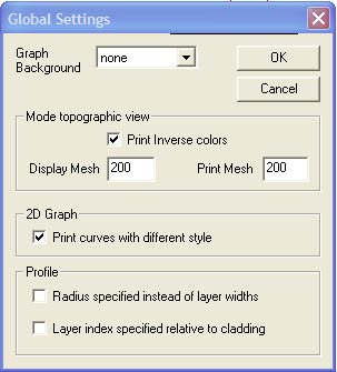
The Global Settings dialog box can be used to change OptiFiber’s style of data entry
and presentation according to user preference. The information in the Global Settings
dialog box will be stored in the system registry. This means that the settings are
remembered after OptiFiber is closed, and will remain in effect on the current
computer until changed by this dialog box. The illustration shows the dialog box with
its default settings. To access this dialog box, select Tools >> Settings …
The elements and controls of the “Global Settings” dialog box options are described
below.
Graph background
Refers to the graph background in the Views window. The available options are: none,
wood, paper, and wall.
Mode topographic View
This section refers to graph setup for the mode field display and printing. The default
background for the mode field display is black, so you may use the Print Inverse
Colors option.
Display Mesh – Enter the number of points in the X and Y dimension of the mode field
screen display.
Print – Enter the number of points in the X and Y dimension of the mode field printed
picture.
2D Graph
Check Print Curves with Different Styles to distinguish curves on black and white
output prints.
Profile
Radius specified instead of layer widths – In the Fiber Profile dialog box, the profile
is specified as a list of Regions (layers) of various widths. There is a read only field
to show the position (radius) of the selected layer. Check this box if you prefer to enter
the radius of the layer instead of the layer width. With this box checked, the width field
will become read only instead of the position field.
Layer index specified relative to cladding – In the Fiber Profile dialog box, the
refractive index of the selected layer is displayed in the Refr. Index field. Check this
box if you prefer to specify the refractive index relative to the cladding layer instead.
With this box checked, the last layer must be constant, and when the last layer is
selected, the cladding refractive index, Nc, will be displayed in the Refr. Index field.
However, when other layers are selected, the index of current layer relative to the
cladding layer will be shown. Since these differences are typically small, the
difference is multiplied by 1000. When any inner layer is selected, the label of the field
will change to (N – Nc) * 1000, as a reminder that the refractive index is being
specified and displayed as a relative value. The display of refractive index in other
parts of OptiFiber is not changed by this setting.