Optiwave software can be used in different industries and applications, including Fiber Optic Communication, Sensing, Pharma/Bio, Military & Satcom, Test & Measurement, Fundamental Research, Solar Panels, Components / Devices, etc..
OptiSystem is a comprehensive software design suite that enables users to plan, test, and simulate optical links in the transmission layer of modern optical networks.
OptiSPICE is the first circuit design software for analysis of integrated circuits including interactions of optical and electronic components. It allows for the design and simulation of opto-electronic circuits at the transistor level, from laser drivers to transimpedance amplifiers, optical interconnects and electronic equalizers.
OptiFDTD is a powerful, highly integrated, and user friendly CAD environment that enables the design and simulation of advanced passive and non-linear photonic components.
OptiBPM is a comprehensive CAD environment used for the design of complex optical waveguides. Perform guiding, coupling, switching, splitting, multiplexing, and demultiplexing of optical signals in photonic devices.
OptiFiber The optimal design of a given optical communication system depends directly on the choice of fiber parameters. OptiFiber uses numerical mode solvers and other models specialized to fibers for calculating dispersion, losses, birefringence, and PMD.
Emerging as a de facto standard over the last decade, OptiGrating has delivered powerful and user friendly design software for modeling integrated and fiber optic devices that incorporate optical gratings.
OptiConverge is a collaborative integration framework that seamlessly combines two or more Optiwave products (e.g., OptiSystem, OptiSPICE, OptiFDTD, etc.) and other third party products into unified solutions. Designed to streamline complex workflows, it empowers users to achieve their goals faster by harnessing the collective power of our trusted Optiwave tools.
The process of designing a new fiber usually starts by defining its profile. Click the
“Fiber Profile” icon in the Navigator pane or double-click the workspace or select the
“Fiber/Profile” menu item.
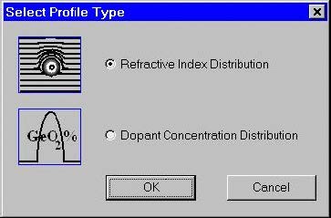
Currently two types of profiles are supported: refractive index profile and dopant
concentration profile. The “Select Profile Type” dialog box offers a choice between
them.
After that the “Fiber Profile” dialog box appears. In case the user has selected
refractive index profile type, it looks as shown:
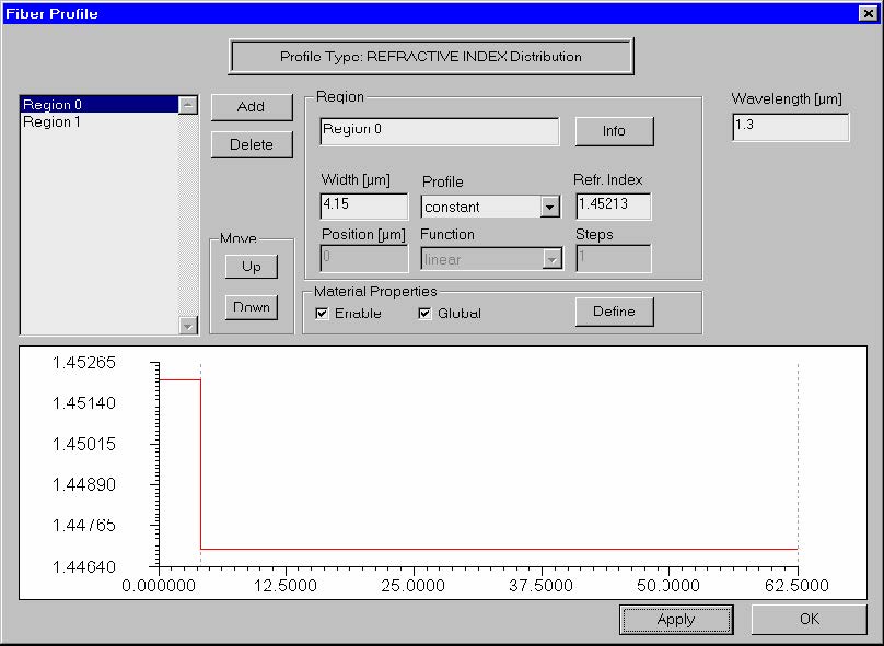
To create a simple step-index fiber (similar to SMF-28) do the following steps:
Step
Action
1
In the “Fiber Profile” dialog box, click the “Add” button twice to create two radial index regions: “Region 0” and “Region 1”. These two regions will represent the fiber core and cladding, respectively.
2
Select “Region 0” on the list and enter its Width value 4.15 microns, then select the “Profile” option as “Constant”, and enter the “Refr. Index” value 1.45213.
3
Press “Apply”.
4
Select “Region 1” on the list and enter its “Width” value 58.35, then select the “Profile” option “Constant”, and enter the “Refr. Index” value 1.44692.
5
Press “Apply”.
6
Enter the “Wavelength” value 1.3.
7
Press “Apply”.
8
Press “OK” to close the “Fiber Profile” dialog box.
You just designed a simple fiber profile that is shown at in the graph pane at the
bottom of the dialog box. The fiber profile is defined at the wavelength 1.3 microns.
If in “Select Profile Type” dialog box the user has selected “dopant concentration type”
then the ‘Fiber Profile” dialog box looks as shown:
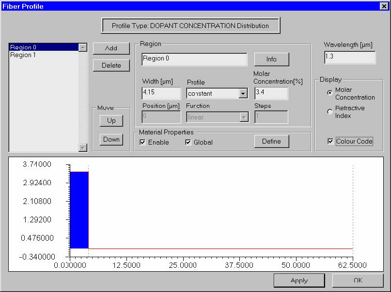
The difference from the previous case is that now the user enters the values of the
molar concentration percentage of the dopant in the edit box where the refr. index
values were entered. This dialog box contains also an additional group of controls –
“Display” – allowing viewing of the profile as a refr. index or concentration type one,
and to color-code the regions. The latter feature is useful for distinguishing
neighboring regions: 1) having equal refr. indices but doped with different
concentrations of different materials, or 2) doped with equal concentrations of
different materials, thus having different refr. indices. The fiber shown in the picture
above is equivalent to the one in the previous picture.