Optiwave software can be used in different industries and applications, including Fiber Optic Communication, Sensing, Pharma/Bio, Military & Satcom, Test & Measurement, Fundamental Research, Solar Panels, Components / Devices, etc..
OptiSystem is a comprehensive software design suite that enables users to plan, test, and simulate optical links in the transmission layer of modern optical networks.
OptiSPICE is the first circuit design software for analysis of integrated circuits including interactions of optical and electronic components. It allows for the design and simulation of opto-electronic circuits at the transistor level, from laser drivers to transimpedance amplifiers, optical interconnects and electronic equalizers.
OptiFDTD is a powerful, highly integrated, and user friendly CAD environment that enables the design and simulation of advanced passive and non-linear photonic components.
OptiBPM is a comprehensive CAD environment used for the design of complex optical waveguides. Perform guiding, coupling, switching, splitting, multiplexing, and demultiplexing of optical signals in photonic devices.
OptiFiber The optimal design of a given optical communication system depends directly on the choice of fiber parameters. OptiFiber uses numerical mode solvers and other models specialized to fibers for calculating dispersion, losses, birefringence, and PMD.
Emerging as a de facto standard over the last decade, OptiGrating has delivered powerful and user friendly design software for modeling integrated and fiber optic devices that incorporate optical gratings.
OptiConverge is a collaborative integration framework that seamlessly combines two or more Optiwave products (e.g., OptiSystem, OptiSPICE, OptiFDTD, etc.) and other third party products into unified solutions. Designed to streamline complex workflows, it empowers users to achieve their goals faster by harnessing the collective power of our trusted Optiwave tools.
Let us consider the well-known basic four-channel Mach-Zehnder multi/demultiplexer [5]. The circuit consists of three different Mach-Zehnder interferometers (MZI) [[1] p. 160], where each MZI has a different arm length. This multiplexer is designed to “collect” the signal of different wavelengths from 1500 nm to 1550 nm introduced from different inputs into the output named C with the channel separation 7.5 nm (for details, see [5]).
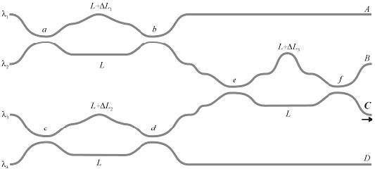
The device can be fully analyzed by the BPM, however we can show it is not necessary. The distances among the input ports (named with the respect to multiplexed wavelengths) are typically 0.25 mm and the device is several millimeters long, the circuit area is quite large. Note, the speed of the BPM simulator is approximately proportional to the layout area. Further, we can see that the layout is, say, somehow coarse, i.e. we can declare some places where the field exists in the evanescent form and the field is negligible. Running the simulation through these places is inefficient, however we cannot exclude these “dead places” from the rectangular simulation window. Our new approach proposes an elegant solution (see the pertinent paragraph below).