Optiwave software can be used in different industries and applications, including Fiber Optic Communication, Sensing, Pharma/Bio, Military & Satcom, Test & Measurement, Fundamental Research, Solar Panels, Components / Devices, etc..
OptiSystem is a comprehensive software design suite that enables users to plan, test, and simulate optical links in the transmission layer of modern optical networks.
OptiSPICE is the first circuit design software for analysis of integrated circuits including interactions of optical and electronic components. It allows for the design and simulation of opto-electronic circuits at the transistor level, from laser drivers to transimpedance amplifiers, optical interconnects and electronic equalizers.
OptiFDTD is a powerful, highly integrated, and user friendly CAD environment that enables the design and simulation of advanced passive and non-linear photonic components.
OptiBPM is a comprehensive CAD environment used for the design of complex optical waveguides. Perform guiding, coupling, switching, splitting, multiplexing, and demultiplexing of optical signals in photonic devices.
OptiFiber The optimal design of a given optical communication system depends directly on the choice of fiber parameters. OptiFiber uses numerical mode solvers and other models specialized to fibers for calculating dispersion, losses, birefringence, and PMD.
Emerging as a de facto standard over the last decade, OptiGrating has delivered powerful and user friendly design software for modeling integrated and fiber optic devices that incorporate optical gratings.
OptiConverge is a collaborative integration framework that seamlessly combines two or more Optiwave products (e.g., OptiSystem, OptiSPICE, OptiFDTD, etc.) and other third party products into unified solutions. Designed to streamline complex workflows, it empowers users to achieve their goals faster by harnessing the collective power of our trusted Optiwave tools.
Devices Consisting of the Combination of BPM & Gratings (“Add/Drop”)
Home » Blog » Devices Consisting of the Combination of BPM & Gratings (“Add/Drop”)
Compatibility:
In this category, we shall study the devices, where a grating is present, BPM is unsuitable (see Figure 5). Of course, as it was mentioned we can use CMT, i.e. the OptiGrating product. At this point, we may recognize the final item of our new method. To analyze some advanced structures by means of several independent techniques, we will have to connect all the particular results using some common way. Moreover, we will need a common environment to do so.
Concerning the functionality of the circuit, two identical Bragg gratings are designed to have the reflection maximum, say, at λ0 =1550nm . For example, the principal parameters of the sine groove grating are as follows: L = 5mm , Δ n = 0.0007 .
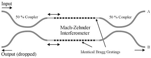
Figure 5: Mach-Zehnder interferometer
The device functionality is quite simple. It is the well-known Mach-Zehnder interferometer, where the arms contain an identical Bragg grating. If the wavelength of the light launched into the input port is far from the grating resonant wavelength λ0 , the light does not “see” any grating and the light thus recombines at the output coupler and emerges in the lower output port (called “B” in the following). However, when the launched light has the wavelength close to λ0 = 1550nm , a portion (the reflection should be 100% at λ0 in the case of an ideal Bragg grating) of the light is reflected by each arm and then recombines at the first/input coupler. The light is thus dropped in the lower left (“input”) port.