The aim of this material is to show the possibilities of using OptiSystem to analyze CATV systems.
In Part I, we demonstrate the basic nonlinear distortions that result from the propagation of the multiple carrier frequencies through a laser diode.
Observation of harmonic and intermodal products is presented. Although the appearance of the nonlinear distortions is a deterministic process, it is considered to contribute to the laser noise.
In Part II, as a typical application example, direct modulation of a laser diode is considered.
We analyze:
a) laser frequency response
b) laser clipping with single sinusoid modulation
c) RIN
d) propagation of the signal with harmonic distortions, RIN and phase noise through standard fiber
To demonstrate these topics, different layouts in the sample file have been designed.
Global parameters of the layouts have been chosen to allow enough frequency resolution for the reliable observation of the studied phenomena. We used a sample rate 160 GHz, and a number of points 65536, with 2.44 MHz frequency resolution.
In most of the cases, our laser diode (described by the laser rate equation component) has threshold current 33.457 mA, bias current 38 mA, and modulation peak current 3.8 mA.
In some cases, in order clearly to observe different effects, RIN and phase noise of laser diode, and noise sources in PIN were disabled.
Part Basic Nonlinear Distortions
Harmonic distortions
For the analysis of harmonic distortions (layout Harmonic distortions), we use one-tone modulation ƒ1 at 500 MHz.
The values of carrier generator amplitude are swept: 0.001, 0.1,0.2, 0.8, 1, 1.2, and 1.5. Both the RIN and phase noise of laser rate equations and noise sources in PIN are disabled.
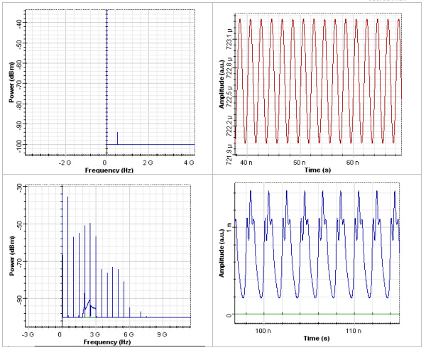
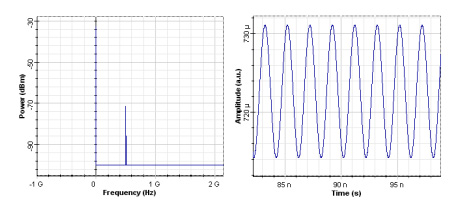
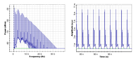
In the following figures, the spectrums and time domain shapes of the signal from the first (initial signal) and fourth iterations are presented.
Figure 1: Harmonic distortions
As we can see, the harmonic distortions can be seen at the tones nƒ1, n is the integer number. The appearance of the new harmonic frequencies in the spectrum leads to a shape deformation of the signal in time, which can be seen in the fourth graph.
We also perform an analysis of the dependence of the magnitudes of the harmonic products as a function of the modulation index. This is accomplished by means of the layout Harmonic distortions modulation index.
In this layout, the modulation index is swept through the change of the amplitude of the carrier generator (between 0.001 and 0.4).
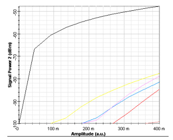
The powers of the original signal at ƒ1 = 500 MHz, and the harmonics at 2ƒ1 = 1 GHz, 3ƒ1 = 1.5 GHz, 4ƒ1 = 2 GHz, 5ƒ1 = 2.5 GHz, and 6ƒ1 = 3 GHz, are measured with the Electrical Carrier Analyzer.
Results are shown in the next figure, where the black, yellow, green, pink, red, and the second pink (just at the bottom right corner of the figure) curves correspond to 500 MHz, 1GHz, 1.5 GHz, 2 GHz, 2.5 GHz, and 3 GHz, respectively.
Figure 2: Magnitudes of the harmonic products
As we can see, the software allows the detailed quantitative analysis of the development of the different harmonic distortions.
Intermodulation distortions
For the analysis of intermodulation distortions (layout Intermodulation distortions), two-tone modulation is applied ƒ1 = 500MHz, ƒ2 = 525MHz.
To change the modulation index, the amplitude of the carrier generator is swept between 0.001and 0.15. Both the RIN and phase noise of laser rate equations, and noise sources in PIN were disabled.
In all cases, the product of 3.8 mA with the amplitude of the carrier generator (which gives the modulation index) is smaller than 38-33.457 = 4.543 mA.
Therefore, we cannot expect laser clipping.
Proceeding through the five iterations of the RF Spectral Analyser_1, we will see the appearance of new intermodulation products: second- and third-order intermodulation distortions.
The second-order intermodulation distortions will be given by |ƒ1-ƒ2| = 25MHz and |ƒ1 + ƒ2| = 1025MHz.
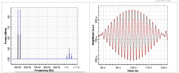
In the following figures, the spectrum and corresponding time-domain form of the signals is shown.
Figure 3: Spectrum and corresponding time-domain form of the signals
In the first figure we see on the left our original frequencies: ƒ1 = 500MHz, ƒ2 = 525MHz.
On the right side of the first figure, we see the second-order distortion |ƒ1 + ƒ2| = 1025MHz (the largest between the three components), and the next order of the second-order distortions between ƒ3 = |ƒ1 + ƒ2| = 1025MHz, and ƒ4 = |ƒ1 – ƒ2| = 25MHz, namely ƒ5 = |ƒ3 + ƒ4| 1.05GHz, and ƒ6 = |ƒ3 – ƒ4 = 1GHz.
The corresponding time shape of the signal is shown in the second figure.
Let us now continue with the analysis of third-order intermodulation distortions. The third-order distortions will be given by |2ƒ1 – ƒ2| = 475MHz (also called two-tone third-order IM products), and |2ƒ1 + ƒ2| = 1525MHz, respectively.
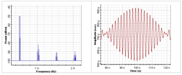
The following figure shows the results from the calculation of the fifth iteration of this layout.
Figure 4: Calculation of the fifth iteration
In the first figure we see already four groups of frequencies.
The first group is our initial two-tone signal.
The second group has been explained by second-order distortions.
The third group consists of two frequencies components:
ƒ7 = |2ƒ1 + ƒ2| = 1.525 GHz, and ƒ8 = |2(ƒ1 + ƒ2) – ƒ1| = 1.55GHz.
As we can see, both of these frequency components are related to the corresponding two-tone third-order IM distortions.
The frequencies in the fourth group are ƒ9 = 2.025GHz, ƒ10 = 2.05GHz, and ƒ11 = 2.075GHz.
They can be interpreted as following triple-beat IM products: ƒ9 = |ƒ7 + ƒ8 – ƒ5|, ƒ10 = |ƒ7 + ƒ8 – ƒ3, and ƒ11 = |ƒ7 + ƒ8 – ƒ6|.
The further increasing of the number of the intermodulation products leads ultimately to deformation of the time shape of the signals.
The contributions of the different second-order and third-order intermodulation distortions (triple-beat IM products and two-tone IM products) can be estimated precisely using the Electrical Carrier Analyzer in the way already demonstrated in the layout Harmonic distortions.
Using standard formulas, the composite second order (CSO) and composite triple beat (CTB) can be calculated that describe the performance of the arbitrary multichannel AM links.
Direct Modulation of Laser Diode
Laser frequency response
Next, we analyze the laser frequency response.
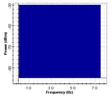
We use a carrier generator, which creates 298 channels with 25 MHz frequency separations, starting at 50 MHz. This initial signal can be seen in the figure below:
Figure 5: 298 channels with 25 MHz frequency separations
This signal is applied to the laser diode. The RF spectrum analyzer is used after the PIN in order to display the laser frequency response. Noise and phase noise of laser rate equations, and noise sources in our PIN were disabled.
In this project, three different values of the amplitude of the carrier generator were used: 0.001, 0.01, and 0.8.
For only the first value, we drive the laser without generating laser nonlinearities. This is the way to obtain the correct laser frequency response.
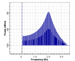
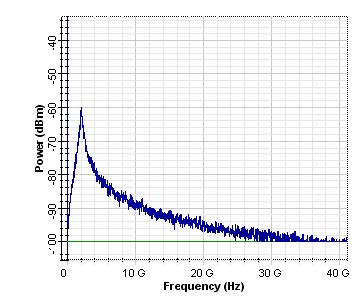
For a laser driver without nonlinearities (iteration 1, the amplitude of the carrier generator = 0.001), the observed frequency response of our directly modulated laser is shown in the next figure.
Figure 6: Frequency response of our directly modulated laser
As can be seen, for the default values of the physical parameters of our laser rate equation model, the relaxation frequency is approximately 2 GHz.
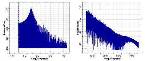
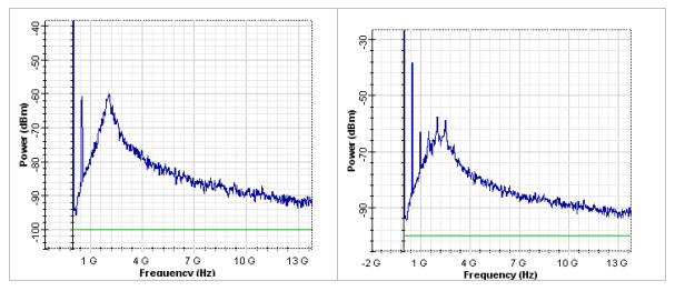
By increasing the values of the amplitude of the carrier generator, the nonlinearities of the laser are triggered. As a result, the observed frequency response changes dramatically. The obtained results for the displayed output for the next two iterations can be seen in the next two figures.
Figure 7: Output for the next two iterations
Clipping
For the analysis of clipping (layout Clipping), the amplitude of the carrier generator is fixed at 0.25.
In this case, the modulation peak current is swept between 0.2, 11.5, 21, 30.5, and 40. Noise and phase noise of laser rate equations, and noise sources in our PIN were disabled.
In this case, the modulation peak current is swept between 0.2, 11.5, 21, 30.5, and 40. Noise and phase noise of laser rate equations, and noise sources in our PIN were disabled.
Figure 8: First iteration
After the third iteration, the drive current goes below a threshold and the laser output power goes to zero in the time domain presentation of the signal. This phenomenon is called clipping. Clipping is best demonstrated in the fifth iteration.
Figure 9: Third iteration
RIN
Here we analyze the relative intensity noise (RIN) of our laser diode.
In our laser rate equation model, we enabled the option Include noise in the Noise tab. Noises in PIN were disabled.
We will sweep the amplitude parameter of carrier generator: 0.001, 0.045, and 0.6.
Note that in this layout, we increased the resolution bandwidth in the RF Spectrum analyzer to 50 MHz.
Contribution from harmonic distortions is minimal in the first iteration. A typical spectral presentation of RIN is observed by using the RF Spectrum analyzer.
Figure 10: Spectral presentation of RIN is observed by using the RF Spectrum analyzer
RIN spectral dependence peaks at frequency 2 GHz.
As mentioned previously, at the same frequency, the maximum laser frequency response was seen. The same default values of the physical parameters of the laser model have been used. This is what we expect from the laser theory.
In the next two figures, we illustrate the relative intensity noise in the presence of harmonic distortions.
Figure 11: Relative intensity noise in the presence of harmonic distortions
Note the appearance of the harmonics at the top of the RIN spectrum (50 MHz resolution bandwidth in the RF Spectrum analyzer has been used.)
Next, we analyze the power dependence of the RIN.
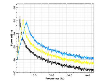
It is well known that increasing the power lead to the reduction of RIN peak. This effect is demonstrated with the Layout RIN power dependence.
Here, we swept the bias current between 38, 58, and 68 A. As a result, the average power changes from 0.72 mW to 2.3 mW, and 5.5 mW.
The observed RIN spectrums are shown in the next figure, where black, yellow, and blue correspond to 0.72 mW to 2.3 mW, and 5.5 mW, respectively.
Figure 12: Decrease in the peak of the RIN with the increase of the power
The expected decrease in the peak of the RIN with the increase of the power can be clearly observed.
Harmonic distortions, RIN, phase noise and propagation in 50 km SMF
Here we continue to analyze the influence of the relative intensity noise of our laser rate equation model on the harmonic distortions – layout RIN phase noise fiber.
In our laser rate equation model, we enable the options Include noise and Include phase noise in the Noise tab. Noise sources in PIN are disabled. We use the amplitude parameter of carrier generator 0.6. The resolution bandwidth in the RF Spectrum analyzer is 50 MHz.
We propagated our signal through 0, 10, and 50 km SMF. The parameters of the fiber can be seen in the tabs of the fiber component.
The corresponding results are shown in the next three figures.
Figure 13: Powers of all signals were reduced by approximately 20 dB
As we can see, at 50 km, due to the linear losses, the powers of all signals were reduced by approximately 20 dB.
If the power of the input light radiation is increased, a complex interaction between the harmonics generated in the laser will occur in the optical fiber because of the fiber nonlinearities.


