Optiwave software can be used in different industries and applications, including Fiber Optic Communication, Sensing, Pharma/Bio, Military & Satcom, Test & Measurement, Fundamental Research, Solar Panels, Components / Devices, etc..
OptiSystem is a comprehensive software design suite that enables users to plan, test, and simulate optical links in the transmission layer of modern optical networks.
OptiSPICE is the first circuit design software for analysis of integrated circuits including interactions of optical and electronic components. It allows for the design and simulation of opto-electronic circuits at the transistor level, from laser drivers to transimpedance amplifiers, optical interconnects and electronic equalizers.
OptiFDTD is a powerful, highly integrated, and user friendly CAD environment that enables the design and simulation of advanced passive and non-linear photonic components.
OptiBPM is a comprehensive CAD environment used for the design of complex optical waveguides. Perform guiding, coupling, switching, splitting, multiplexing, and demultiplexing of optical signals in photonic devices.
OptiFiber The optimal design of a given optical communication system depends directly on the choice of fiber parameters. OptiFiber uses numerical mode solvers and other models specialized to fibers for calculating dispersion, losses, birefringence, and PMD.
Emerging as a de facto standard over the last decade, OptiGrating has delivered powerful and user friendly design software for modeling integrated and fiber optic devices that incorporate optical gratings.
OptiConverge is a collaborative integration framework that seamlessly combines two or more Optiwave products (e.g., OptiSystem, OptiSPICE, OptiFDTD, etc.) and other third party products into unified solutions. Designed to streamline complex workflows, it empowers users to achieve their goals faster by harnessing the collective power of our trusted Optiwave tools.
Long-haul 100 Gbps and higher data rate DWDM transmission systems.
High-speed multi-mode fiber transmission for interconnects in data centers and high performance computing.
Optical Ethernet in Automotive.
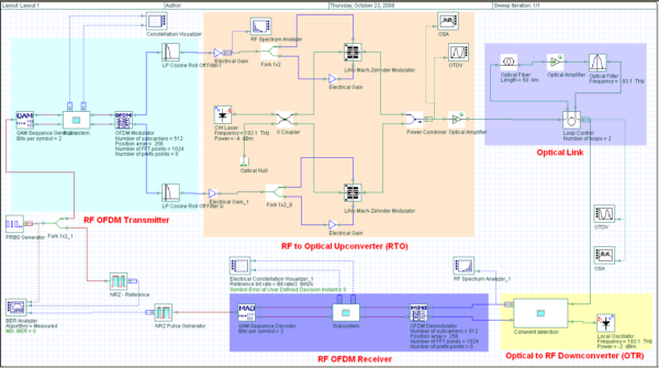
Coherent Optical OFDM Layout
Benefits
Multi-parameter scanning enables system designers to study trade-offs with respect to parameters of interest and to choose an optimal design for deployments.
Interfaces with popular design tools.
New BER Test Set enables the simulation of millions of bits for direct error counting.
Simulation Description
A generic CO-OFDM system includes five basic functional blocks: OFDM transmitter, RF to optical (RTO) up-converter, optical link, optical to RF (OTR) down-converter, and OFDM receiver. The above schematic demonstrates a 10 Gbps coherent 512-subcarrier 4-QAM OFDM system; however the input data for the OFDM modulator can have different modulation formats such as BPSK, QPSK, QAM, etc. At the transmission block, both modulation and multiplexing are achieved digitally using an inverse fast Fourier transform (IFFT). The subcarrier frequencies are mathematically orthogonal over one OFDM symbol period. A CW laser and two Mach-Zehnder modulators are used to up-convert the RF data to the optical domain. The signal is then propagated through the optical link and becomes degraded due to fiber impairments. A coherent receiver with a local oscillator is used to down-convert the data to the RF domain, and finally data is demodulated and sent to the detector and decoder for BER measurements.
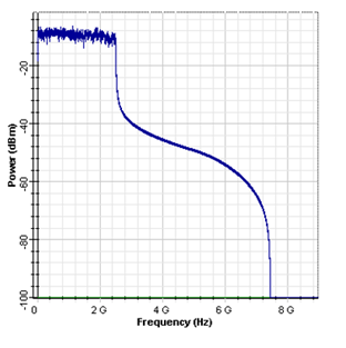
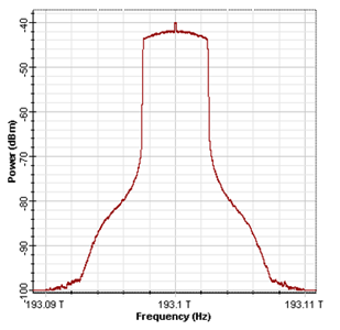
The RF spectrum for the in-phase component and the generated optical OFDM spectrum after I/Q modulation is shown below.
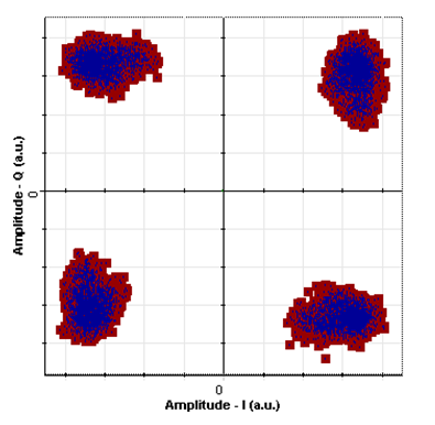
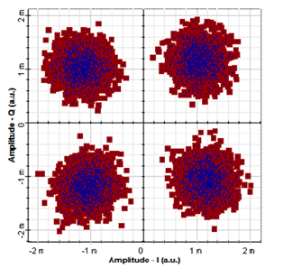
After propagating through 60 km SMF 28 fiber, the recovered signal constellation diagram at the RF OFDM receiver is shown below.
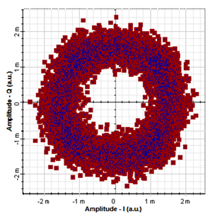
For transmission of an optical OFDM signal over a long length of fiber, electronic dispersion compensation is necessary. As an example, a 10 Gbps coherent 4-QAM OFDM is transmitted through a 3000km SMF 28 fiber link. The received signal constellation diagram with and without electronic dispersion compensation is presented here: