Optiwave software can be used in different industries and applications, including Fiber Optic Communication, Sensing, Pharma/Bio, Military & Satcom, Test & Measurement, Fundamental Research, Solar Panels, Components / Devices, etc..
OptiSystem is a comprehensive software design suite that enables users to plan, test, and simulate optical links in the transmission layer of modern optical networks.
OptiSPICE is the first circuit design software for analysis of integrated circuits including interactions of optical and electronic components. It allows for the design and simulation of opto-electronic circuits at the transistor level, from laser drivers to transimpedance amplifiers, optical interconnects and electronic equalizers.
OptiFDTD is a powerful, highly integrated, and user friendly CAD environment that enables the design and simulation of advanced passive and non-linear photonic components.
OptiBPM is a comprehensive CAD environment used for the design of complex optical waveguides. Perform guiding, coupling, switching, splitting, multiplexing, and demultiplexing of optical signals in photonic devices.
OptiFiber The optimal design of a given optical communication system depends directly on the choice of fiber parameters. OptiFiber uses numerical mode solvers and other models specialized to fibers for calculating dispersion, losses, birefringence, and PMD.
Emerging as a de facto standard over the last decade, OptiGrating has delivered powerful and user friendly design software for modeling integrated and fiber optic devices that incorporate optical gratings.
OptiConverge is a collaborative integration framework that seamlessly combines two or more Optiwave products (e.g., OptiSystem, OptiSPICE, OptiFDTD, etc.) and other third party products into unified solutions. Designed to streamline complex workflows, it empowers users to achieve their goals faster by harnessing the collective power of our trusted Optiwave tools.
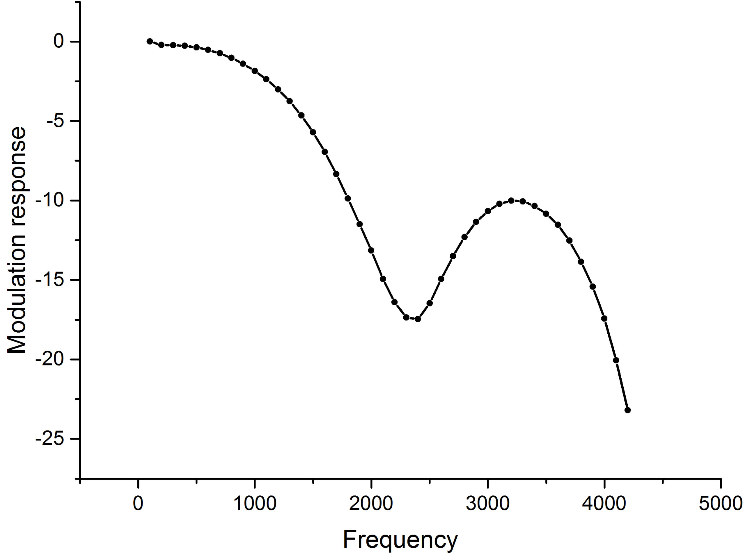
finally, I got the more reasonable modulation response. however the curve starts rising around 2.4GHz as shown in fig. some parameters may not be proper.
Damian, thank you so much for helping me lots on the rsoa module. The modulation bandwidth is still so high, more than 6 GHz when I used the linear gain approximations. I tried to change some parameters. however I havent figured out. any suggestion?
I tried the linear gain approximations, which is generally used for bulk RSOAs. However, the results are not correct. I even cannot get sin waves . I haven’t figured out where the problem is. could you please help me?
Thank you so much for your reply. The modulation bandwidth is generally less than 2GHz in a real RSOA component. the shape is going high from 100 MHz, may be increased by more than 5dB, then going to drop, even if I changed some parameters.
as you suggested, i can detect the peak around frequency. now the problem is the modulation bandwidth unlike real RSOA which show us low pass property. any suggestion on that? thanks
I have figured out. the code should be as following.
As=1; % amplitude of sine wave
fc=Parameter1*1e9; % sine wave with 15 GHz
fs=Parameter2; % sample rate
tw=Parameter0; % time window
just to upload osd file. it maybe has problem to pass global parameters sample rate and time window to matlab. but even I used fs=640e9; tw=12.8e-9; the output is still null.
is it possible to set the frequency of Quadrature Modulator to 0 Hz in order to get a baseband signal? and how to set the quadrature demodulatr cutoff frequency?