
Base
| Full Name | Tu Nguyen |
| Organization | UMONS |
| Job Title | RA |
| Country |
Forum Replies Created
Thank you for the gift card! I appreciate that.
Is there any one who suffered the purchasing problem like me?
I do not know why I cannot apply the 20USD gifted credit to purchase things. When I tried to purchased thing less than 20 USD, the “continue” button was hidden and It told that “please enter your payment information to continue”. I already ticked to use the gift card, and I also selected the payment method, as well as all information about the shipment address.
Thank you,
Hi,
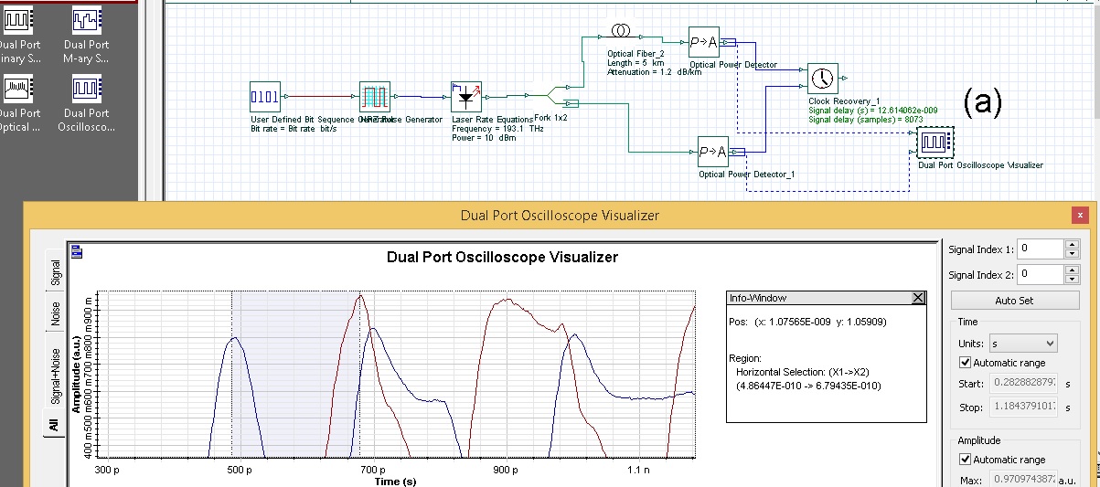
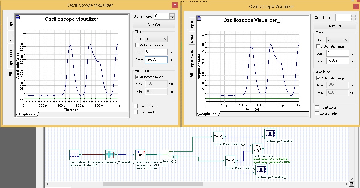
I found that sometime the result of optisystem is not so reliable. I dont know why, or is there any problem with my simulation. I just run this sample simulation to calculate the delay but I cant understand why it goes like that.
– look at figure 1, I see that the delay time is ~12.6ns, however, I see in the figure, it should be ~0.2ns.
– at figure 2, I discarded the fiber, and of course, both signal are exactly the same. however, the delay module tells me that there is still 12.8 ns in delay.
What is the point I missed?
I attached the figures and the model as well,
Many thanks if you have a short look.
Thank you! yes, I agree, we can add multiple matlab components in a project. It runs, but how to differ signals belonging to each component in the Workspace? I used two Matlab components but I can only see the only one InputPort1 data in Workspace. How to see the other one?
Thank you
Thank you, I have found out the problem.
So, I wonder can we use more than one matlab component in the same project?is it ok? if it is fine, I think that the in/output’s names of different matlab components should be separated, but I dont know how to separate them without changing the default names.
Thank you
Thank you,
Since I did not see my post so I thought that there was an error in network connection. I am sorry!
Good afternoon,
Thank you for your contribution!
Would you please check whether the simulation file I attached bellow runs successfully or not? I try to run it but the program stops and terminates automatically all the time.
Thank you.
thank you for your upload
Thank you! I checked again and reinstalled, but nothing happens. Can you show me where I can download the “OptiSystem_Samples.exe ” executable to run? I installed OptiSystem by the executive file named “OptiSystem_13_64-bit.exe”
Thank!
Does anyone see the sample folder after setting the OptiSystem 13 up? I read help section and it is said like “These examples can also be found in OptiSystem 13 samples/Transmitter design and analysis/LiNb_Modulator_Settings.osd” but actually, I cannot find out the samples folder. What is wrong with it? Thank you!
Thank you all, I got the point. some functions actually are embeded by matlab code and of course, we cannot look inside.
And does any one who get the .osd files of assingment examples (http://staging.optiwave.com/resources/academia/optisystem-lab-assignments/) which are run by OptiPerformer? I am playing with Optisytem 13 trial version and I want to look into all parameters of examples reather than some changable parameters.
Thank you!
Thank you. Actually, I cannot access into the RX, TX and DSP blocks in that example. I want to look insight in order to see how it is designed. I think that maybe It cannot be accessible with trial version. I am not sure whether my thinking is right or not. Or maybe these blocks are the “hard built” and we can not modify it. I do not think so… therefore, I assume that it is because of trial version? right?
Thank you so much for providing me more detailed information.
I am now experiencing some of the samples with OptiSystem (trial version). It is quite simple to use and understand, however, many of subsystems are not accessible, they are hidden. For example, I am looking at sample “100 Gbps DP-QPSK System with DSP” and actually, I cannot look into the RX, or DSP sub-blocks. Does the tool blocked these sub-systems with the trial version? and will it be opened once we use the licensed tool officially?
Thank you
Thank you very much for your help Ravil and shrama. I already downloaded the desired files following your helps.
I am thinking of using this tool for my PhD research. However, I am now quite confusing a little bit how deep I can monitor into optical devices in OptiSystem. I am not sure since I see many things done completely. It is great to know that the Optisystem can be integrated into Matlab, and it would be more plexibilitle for me. Do you have any documents related to this matter? I see some guides at the library but I wonder are there other documents, more deeply. Thank you very much,
By the way, can you refer me some paper which used OptiSytem for their work? It seems to me that the tool is not usually used to research.
Thank you and have a nice time,