Base
| Full Name | Tayyab Mehmood |
| Organization | NUST |
| Job Title | student |
| Country |
Forum Replies Created
Thanks Damian for replying with such a helpful material. I have done this part too in the optisystem. I am wondering how one can extract both the signals (high priority and low priority) at the receiver side . Would you please help me in this regard.
Still, did not find a solution to do hierarchical modulation in Optisystem 14.0. But succeeded to do hierarchical modulation in MATLAB.
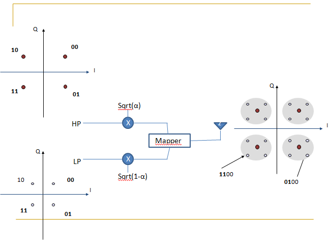
Here is the basic conceptual diagram of hierarchical modulation in the electrical domain
Attachments:
Hi Dhiman, Send/message me your email ID. I will send you the collection of books.
Regards
Hi dhiman I have a collection of ROF related books, I am sending the dropbox link for all.
I post my problem in this thread because Hager had the same problem in the beginning of this thread.
I still did not figure it out whats wrong with the DPSK system.
Regards
Thanks Alistu and Dhiman for replying.
Regards
here are the files
Thanks Dhiman and Alistu for replying,
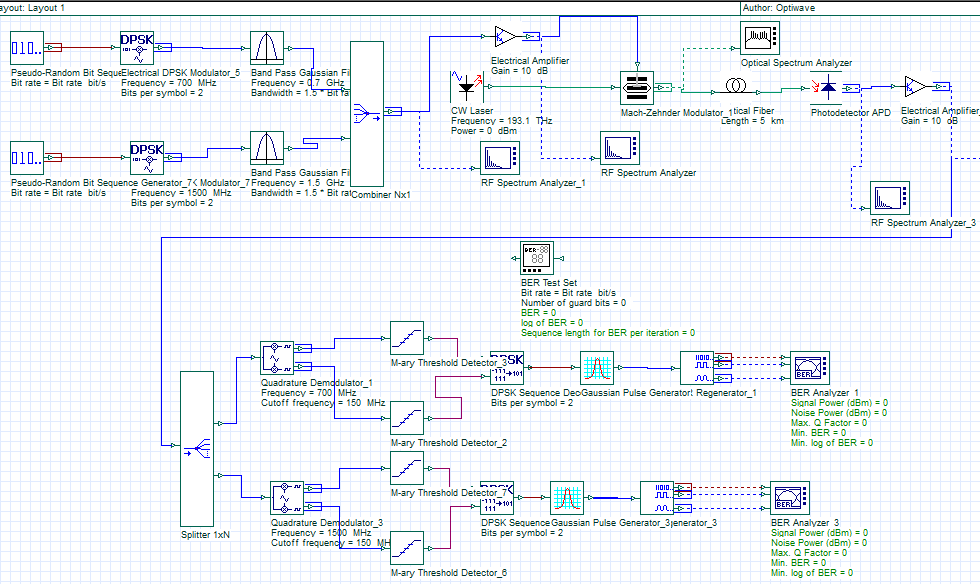
now I increase the bit rate from 240-Mb/s to 24 Gb/s, increase the length of SMF from 5Km to 100 Km and decreases the input power of the laser from 0d dBm to -5 dBm.
Still the BER is zero and now the Q-factor is in thousands.
I think there is a problem with the configured parameters or I am using wrong components for the system.
Kindly help me in this matter.
Regards
After reading the whole topic on Radio over fiber system, I concluded that I have the same problem with my system. Although my system is a bit more simple than the above mentioned system was but I am not getting the desired results (BER=10^-12). currently the BER is 0.
system specifications: bit rate= 240 Mbps ; symbol rate= 120 Msps; bits per symbol= 2 bits;
frequency of first DPSK modulator is 0.7 GHz; frequency of second DPSK modulator is 1.5 GHz.
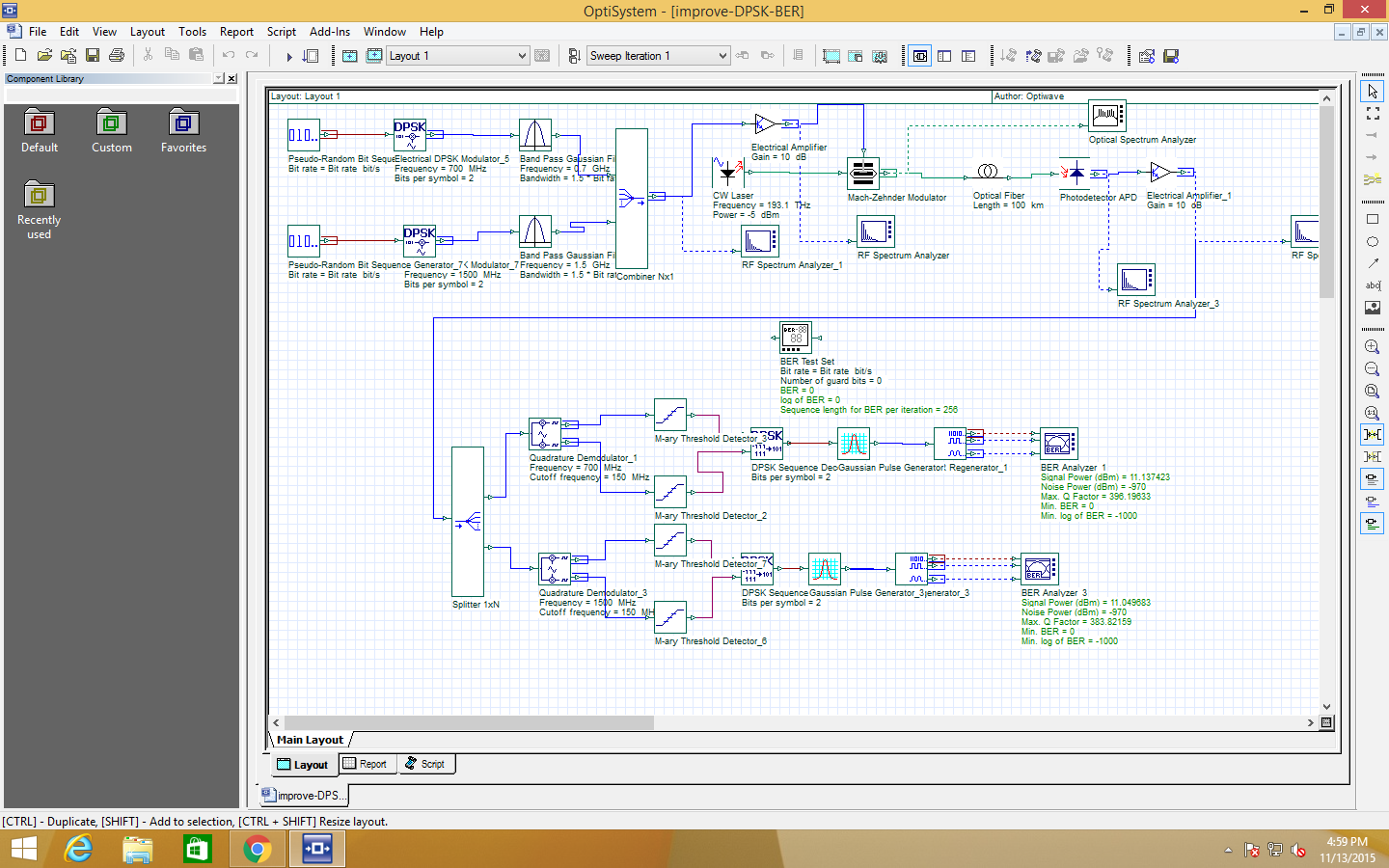
I am attaching the snapshot and the system file below.
Regards
Thanks Sir.
Thanks sir
Respected Sir , checkout the attached files below , I modify the project file and remove optical circulators from both sides , now I get the desired results.
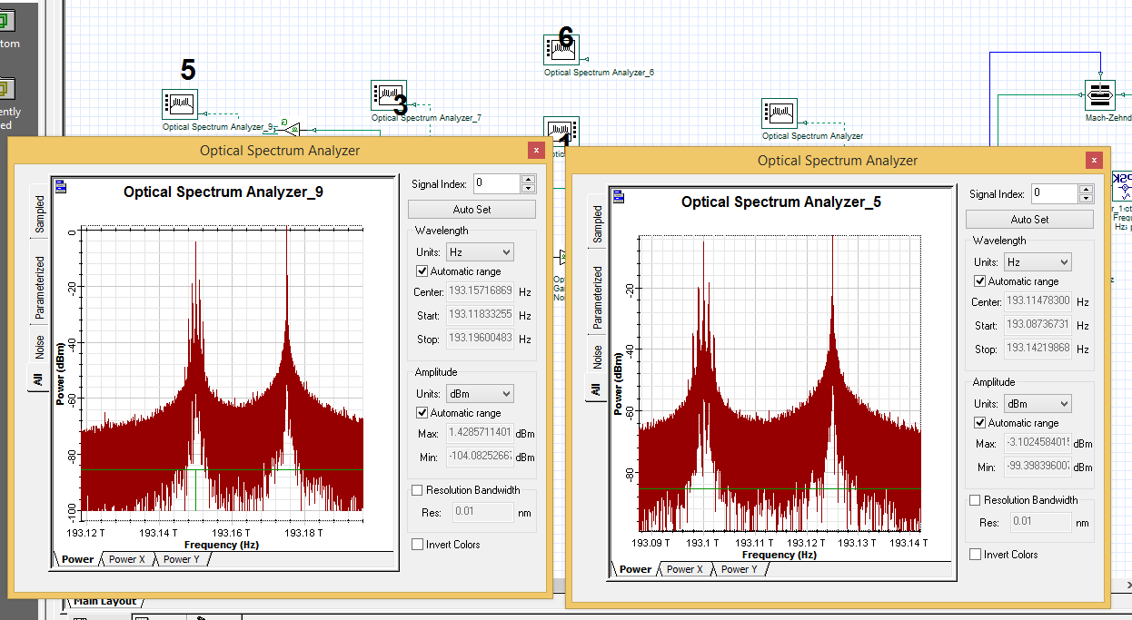
kindly see the figure, which shows the spectrum after the amplifier for uplink and downlink.
Thanks Alistu, I am also working on it and trying to modify the examples related to bidirectional fiber to run this simple bidirectional ROF link.
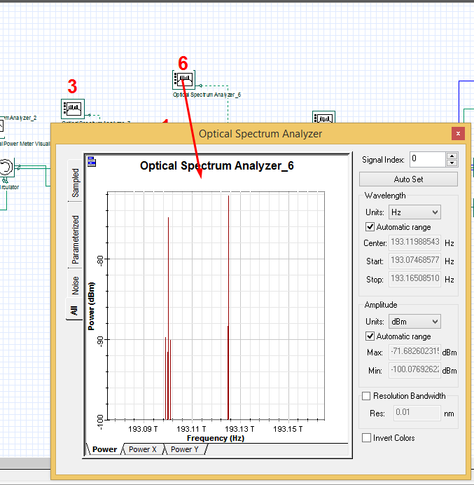
Thanks for replying, but sir problem starts with the uplink, why I am getting the remaining of 193.1 & 193.25 THz at 5 and at 6 ( attached below) and not getting any result at 3 and 4.