Optiwave software can be used in different industries and applications, including Fiber Optic Communication, Sensing, Pharma/Bio, Military & Satcom, Test & Measurement, Fundamental Research, Solar Panels, Components / Devices, etc..
OptiSystem is a comprehensive software design suite that enables users to plan, test, and simulate optical links in the transmission layer of modern optical networks.
OptiSPICE is the first circuit design software for analysis of integrated circuits including interactions of optical and electronic components. It allows for the design and simulation of opto-electronic circuits at the transistor level, from laser drivers to transimpedance amplifiers, optical interconnects and electronic equalizers.
OptiFDTD is a powerful, highly integrated, and user friendly CAD environment that enables the design and simulation of advanced passive and non-linear photonic components.
OptiBPM is a comprehensive CAD environment used for the design of complex optical waveguides. Perform guiding, coupling, switching, splitting, multiplexing, and demultiplexing of optical signals in photonic devices.
OptiFiber The optimal design of a given optical communication system depends directly on the choice of fiber parameters. OptiFiber uses numerical mode solvers and other models specialized to fibers for calculating dispersion, losses, birefringence, and PMD.
Emerging as a de facto standard over the last decade, OptiGrating has delivered powerful and user friendly design software for modeling integrated and fiber optic devices that incorporate optical gratings.
OptiConverge is a collaborative integration framework that seamlessly combines two or more Optiwave products (e.g., OptiSystem, OptiSPICE, OptiFDTD, etc.) and other third party products into unified solutions. Designed to streamline complex workflows, it empowers users to achieve their goals faster by harnessing the collective power of our trusted Optiwave tools.
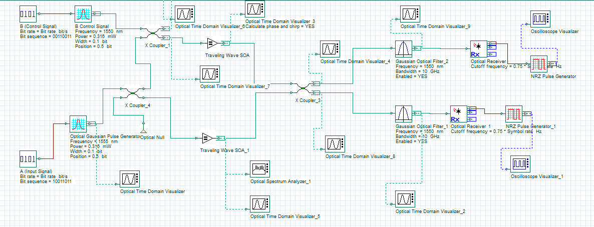
In previous response, faced some upload error for “SOA-MZI.osd” file. Hence, sending the image file for the same.
Kindly check the attached “SOA-MZI.png” file for my design.
I have checked the XOR-gate.osd example in OptiSystem Example Library. In this example both the signals are traveling independent path, i.e., in two different arms without coupling. Moreover, none of the input is acting as a control signal.
However, in my design both optical input signals (A and B) are coupled at coupler C2, where B act as the control signal. The presence and absence of control signal B decides the output at cross port (A.not(B)) and bar port (A.B), respectively.
I have attached my design (SOA-MZI.osd), where output at “Optical Time Domain Visualizer_9” and “Optical Time Domain Visualizer_2” should be equal to bar (A.B) and cross states (A.not(B)), respectively.