Base
| Full Name | shivakumar rjgr |
| Organization | rgpv |
| Job Title | student |
| Country |
Forum Replies Created
hi everyone, i have got the values of FWM in a wdm system and i want to check whether the obtained results are correct or not. please help me how to validate the results. i want to compare fwm of rz and nrz wdm systems
hi everyone,
all i need ask, is there any formula to calculate timing jitter numerically to validate the result that we got from histogram of an eye diagram.thank you
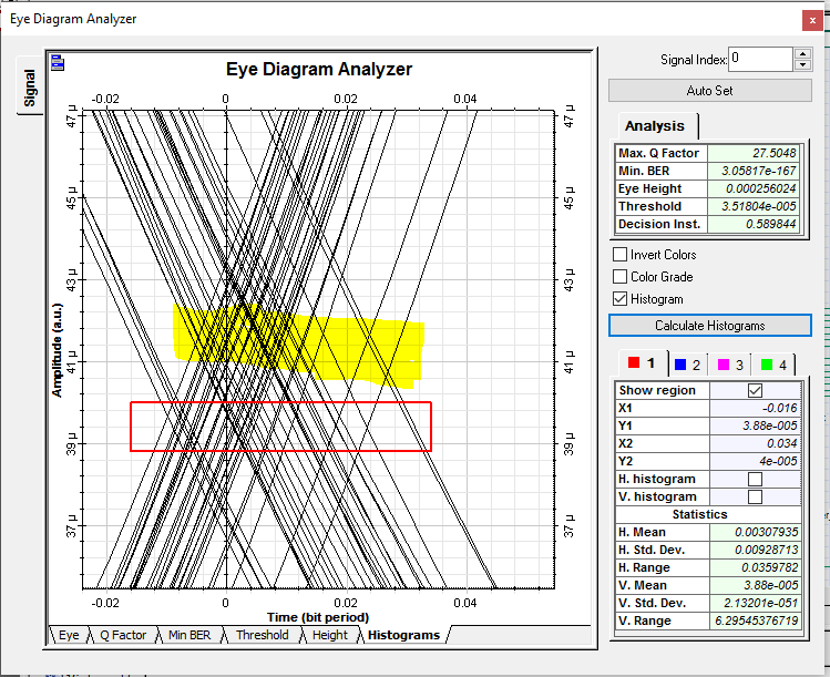
hi,
i’m confused to find the jitter value from the eye digram. i.e., where the exact location of histogram so that the correct jitter value can be obtained. i’m attaching the image of eye diagram and please explain the correct position of histogram.should i consider the red one or yellow one.pls help
Attachments:
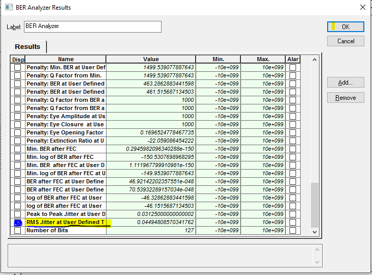
hello everyone,
i HAVE BEEN WORKING ON WDM SYSTEMS.I WANT TO MEASURE THE TIMING JITTER OF THE SYSTEM. PLEASE EXPLAIN TO MEASURE THE JITTER VALUE FROM EYE DIAGRAM. IN RESULTS OF BER ANALYSER, THERE IS A VALUE NAMED ” RMS JITTER AT USER DEFINED THRESHOLD”, COULD IT BE THE JITTER VALUE OF THE SYSTEM.PLEASE HELP