
Base
| Full Name | shaymaa Tahhan |
| Organization | AlNahrain University |
| Job Title | Doctor |
| Country |
Forum Replies Created
Should I put a value in the OFDM POWER in the OFDM modulator?
Yes SER is zero also whenever BER is zero.
1- what is the best bitrate to configure and evaluate the OFDM QAM4 system based on?
because when I increase the bitrate the BER is increasing with SMF distance (take the symbol rate half of the bitrate because I am using QAM 4)
2- if I took the one span (10km SMF, 2km DCF) should I include the length of the DCF in the OFDM demodulator or just the SMF?
if NO, then if I increase the span to 20 the DCF will be 40km is it ok to not include its length?!
whenever I got OFDM EVM less than 5% , the BER readings in the tester is 0
is that realistic or what should I do?
I have tried many times but the same!
need the answer to this question please.
please send me your email address to send you the file.
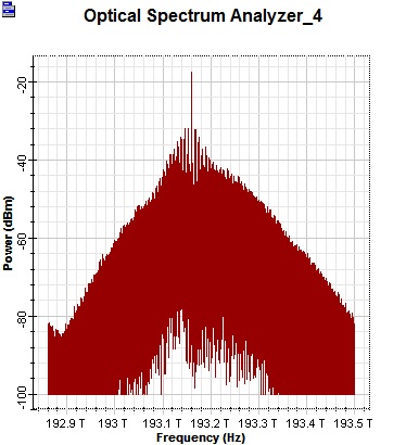
this is the signal after the RSOA
Attachments:
attached is my try in optisystem please correct it for me.
dear sir,
the attached block diagram , the highlighted part of SOA and Modulator.
please advice me how to connect the and please send me an optisystem picture simulate these parts
kind regrads,
Shaymaa
Attachments:
Hello Binh,
did you mean by the BEN the same as digital delay generator shown in the following link
https://www.thinksrs.com/downloads/pdfs/manuals/DG645m.pdf
If yes did you solve your problem ??
kind regards,
Shaymaa
Dear Prof. Mohammed,
this link is the specification sheet for the digital delay generator which i am trying to simulate it
and thhttps://www.thinksrs.com/downloads/pdfs/manuals/DG645m.pdf
hopeful you can help me
Kind regards,
Shaymaa
Thank you for your prompt response. Could you please send me the example any way? I have ver 14 also.
It is very important for me.
Kind Regards
Shaymaa
Dear Sam,
Thank you for your reply. Attached the noise bandwidth of the EDFA that i meant before. thank you for clarification about logarithmic scale.
For now I am only have these two problems
1> what is the noise bandwidth that i should put in the EDFA to get the maximum Qfactor ?
2> what is the required bandwidth of demultiplexer and multiplexer to get the maximum Q factor?
again please find the attached pdf in which all the description of the simulation that I am working on.
Then i want to replace the DCF by FBG to find whether it can be more efficient with duobinary or not?
so how to calculate the length of the FBG ? how to get the Dispersion ?
for Ideal FBG i now that for a length of SMF which has (16 ps/nm km ) the dispesion will be the multiplexing of these values but in minus sign like for 100Km the FBG dispersion will be -1600ps/nm
but for FBG how?
