Optiwave software can be used in different industries and applications, including Fiber Optic Communication, Sensing, Pharma/Bio, Military & Satcom, Test & Measurement, Fundamental Research, Solar Panels, Components / Devices, etc..
OptiSystem is a comprehensive software design suite that enables users to plan, test, and simulate optical links in the transmission layer of modern optical networks.
OptiSPICE is the first circuit design software for analysis of integrated circuits including interactions of optical and electronic components. It allows for the design and simulation of opto-electronic circuits at the transistor level, from laser drivers to transimpedance amplifiers, optical interconnects and electronic equalizers.
OptiFDTD is a powerful, highly integrated, and user friendly CAD environment that enables the design and simulation of advanced passive and non-linear photonic components.
OptiBPM is a comprehensive CAD environment used for the design of complex optical waveguides. Perform guiding, coupling, switching, splitting, multiplexing, and demultiplexing of optical signals in photonic devices.
The optimal design of a given optical communication system depends directly on the choice of fiber parameters. OptiFiber uses numerical mode solvers and other models specialized to fibers for calculating dispersion, losses, birefringence, and PMD.
Emerging as a de facto standard over the last decade, OptiGrating has delivered powerful and user friendly design software for modeling integrated and fiber optic devices that incorporate optical gratings.
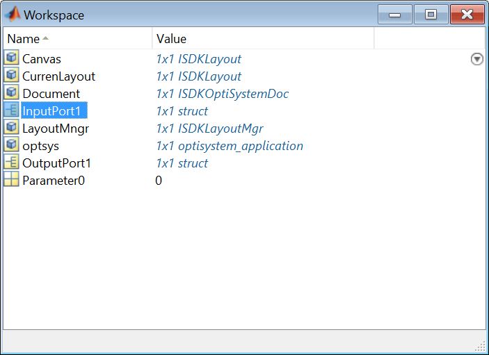
I have already collected the electric field distribution from InputPort1.Sampled.Spatial.ModeX.Amplitude, but I want to know how to calculate the Overlap Integral from the “InputPort1.Sampled.Spatial.ModeX.Amplitude” in Matlab. Is it by using trapz() function in Matlab?
In fact, I want to do some calculations on the coupling coefficients of the input modes to generate new signals (equalize the signals).
In this case, after sending the input data and program the overlap integral inside Matlab to get the coupling coefficients of the input modes. And after doing a calculations on these coupling coefficients, How can I send back the new signal(equalized signals) to the receiver? the OutputPort1 of Matlab component is equal to what??
Where the OutPutPort1 should be included the equalized signals, and the structure of the OutputPort1 of Matlab component, should be similar to the structure of the InputPort1, to be send to the receiver.
Damian Marek, thank you for your prompt response to the question,
(1) Do you mean that, the InputPort1 structer (in Matlab’s workspace), does not include the coupling coefficients?
(2) If the coupling coefficients are calculated in the MMF, why they are not part of the InputPort1 structer?
(3) Is it possible to calculate the coupling coefficients from the input signals?
(4) If I calculate the coupling coefficients from the input signals, is it possible to export them to Matlab?