Optiwave software can be used in different industries and applications, including Fiber Optic Communication, Sensing, Pharma/Bio, Military & Satcom, Test & Measurement, Fundamental Research, Solar Panels, Components / Devices, etc..
OptiSystem is a comprehensive software design suite that enables users to plan, test, and simulate optical links in the transmission layer of modern optical networks.
OptiSPICE is the first circuit design software for analysis of integrated circuits including interactions of optical and electronic components. It allows for the design and simulation of opto-electronic circuits at the transistor level, from laser drivers to transimpedance amplifiers, optical interconnects and electronic equalizers.
OptiFDTD is a powerful, highly integrated, and user friendly CAD environment that enables the design and simulation of advanced passive and non-linear photonic components.
OptiBPM is a comprehensive CAD environment used for the design of complex optical waveguides. Perform guiding, coupling, switching, splitting, multiplexing, and demultiplexing of optical signals in photonic devices.
OptiFiber The optimal design of a given optical communication system depends directly on the choice of fiber parameters. OptiFiber uses numerical mode solvers and other models specialized to fibers for calculating dispersion, losses, birefringence, and PMD.
Emerging as a de facto standard over the last decade, OptiGrating has delivered powerful and user friendly design software for modeling integrated and fiber optic devices that incorporate optical gratings.
OptiConverge is a collaborative integration framework that seamlessly combines two or more Optiwave products (e.g., OptiSystem, OptiSPICE, OptiFDTD, etc.) and other third party products into unified solutions. Designed to streamline complex workflows, it empowers users to achieve their goals faster by harnessing the collective power of our trusted Optiwave tools.
Hi Damien,
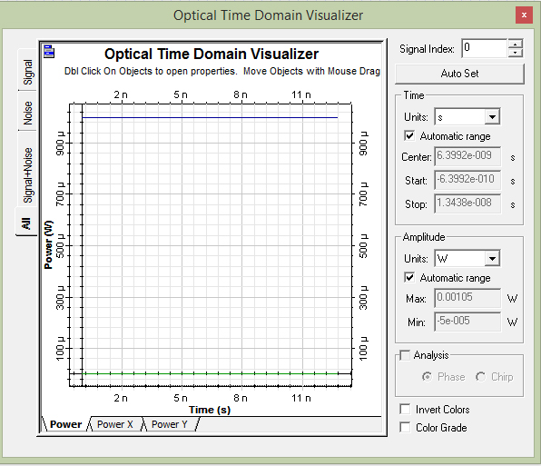
Thank you. there is no errors now. I have modified the project for communication using white led and received the output.
However, why i can”t reduce the frequency of output? or the output which i got is noise? I have changed the bit rate in layout parameter.
Also, the data input to the user defined sequence generator is a binary converted image. I have tried to plot the same in optisystem but not succeeded. But it worked in matlab.
I am attaching the output waveform here
also the .txt file,receiver output and the matlab codes
Hi Damien ,
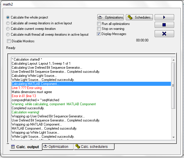
I have checked the noise bins make it true. now matrix dimension mismatch error occurs for seqmatched,
should i match the dimension of seqmatched and InputPort1.Sampled.Signal ? I have checked in workspace and not able to correct this. please help.
I have changed the frequency of white light source to 500 nm
Dear Damien, Thanks.it is working.
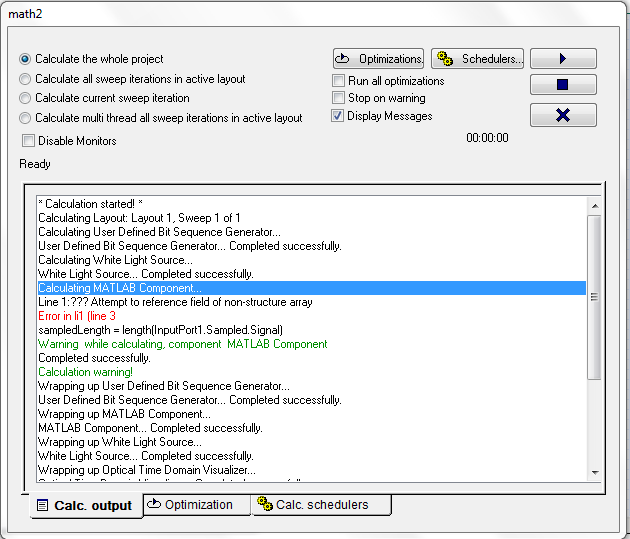
I just replaced the cw laser with a white light source and checked the result. but error occurs. will it be due to sampling problems??
Hi Damien, I have made some changes in my project file according to your suggestions. I am unable to view the output waveform. please help me to solve the issues.
Attaching the .osd file, input file to the user defined sequence generator, matlab code and output waveform
Thank you Damian, It is working now. However the output frequency is very high.
I wanted to load .dat file for the same type of output. Any other things to taken care for this?
Hai sam sung,
I am able to co-simulate the matlab with optisystem. I was just trying out a simple programe code from the demo video. I want to modulate the laser according to the data which can be inputted as .dat file in the user defined sequence. The data is a binary valued(streams of 1’s and 0’s)
Hi Damian,
I am working on the same visible light communiation as that of sindhu kathirvel. I want to input the data (eihter image or audio) which is fed to LED for modulation purpose. I came to know about using matlab component in optisystem. could you help me to solve this problem?
Thanks Abhishek Shrama and Sam Sung for your valuable response. I am having the doubt that even if I am using different modulations at the transmitter side, only one type of demodulation technique is used at the receiver. So can I have the same data at the receiver without using different demodulators?
Dear Sam Sung, May I know how to compare the three modulations in one system?
it would be very helpful if you attach a screen shot of the layout.