
Base
| Full Name | Shahbaz Qureshi |
| Organization | IU |
| Job Title | student |
| Country |
Forum Replies Created
Hi All,
Thank you for your prompt response. I have already performed simulation and designed the system using optisystem. however, i was planning to move towards practical implementation. Any help in this regard will be appreciated.
Hi Everyone,
Thank you for the prompt response. I will try installing another version and change directory then run the file again.
Hi Hoat,
In GPON, all ONUs for upstream uses the same wavelegnth and it is in TDMA manner which means each user transmits signal in a specific time slot. The upstream receiver would receive signal from all ONUs but not at the same time.
Hi Hoat,
I understand. I’ll take a look at your simulation file and get back to you. Meanwhile, take a look at this discussion if it can be of your help and also if you will attach the screenshot I’ll be able to help promptly.
Hi Alistu,
I know about script mode but that is different from what I need help for. TWDM PON has an option of tunability where lasers automatically tune to different wavelengths and similarly filters depending upon the need. Whether they are at transmitter side or receiver side.
I needed help in this regard if we can perform this in Optisystem or we will have to interface another software with Optisystem to perform this task?
Hi Alistu,
You are correct. I forgot to mention about the use of amplifiers. Their use certainly increases the power than the launched power.
Hi San,
Circulators are used to achieve Bi-directional transmission over a single fiber. It is 3 or 4 port device. It separates the signals travelling in opposite direction such that Signal entering port 1 will leave from the port 2. In case, a emitted light is reflected it will exit from another port i.e. port 3.
However, the difference berween circulator, ideal circulator and optical null is very well explained by Alistu above.
Dear San,
Bit rate stays same and it is set at the transmitter side. However, you can measure the received power at the receiver which is always less than the one set at transmitter.
In order to see the bit rate, you can double click and a window will appear. There you can see and change the bit rate according to your system requirements.
Hi Hoat,
Due to the propagation of signal in both directions in bidirectional systems. The propagation should occur at the same time or in real time but this is not possible in simulation because of operations going on both sides. This is why we use optical delay to hold one of the signals until operations on both sides are completed and signals can propagate at the same time like in real time.
Hi Lavanya,
Dhiwan explained it well along with the techniques that can be used. However, I am attaching a link about application of DSP in 100 Gbps DP-QPSK System. Hope this will help you.
LINK:
Thanks for the document, Alistu. It was quite helpful.
Thanks Namera. I understand that now. I was just confused if it would be acceptable or not because it looked a bit different. But I guess I was able to obtain a good Q factor So I can use this eye diagram.
Thanks Alistu. I understand. But the eye diagram attached by Namera for RZ is acceptable? or does it always have to look like the attached one.
Attachments:
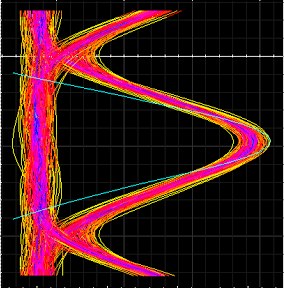
Thanks Namera. Is the eye diagram attached for RZ appropriate? It forms X type of shape below or it can be like this aswell?
Thanks Alistu, I’ll do that. But using a MUX after WDM would be appropriate? it will occur loss.
I tried simulating the system with gain 0 in upstream direction. It worked with a little bit of noise. However, you are right the bug stays there.