Optiwave software can be used in different industries and applications, including Fiber Optic Communication, Sensing, Pharma/Bio, Military & Satcom, Test & Measurement, Fundamental Research, Solar Panels, Components / Devices, etc..
OptiSystem is a comprehensive software design suite that enables users to plan, test, and simulate optical links in the transmission layer of modern optical networks.
OptiSPICE is the first circuit design software for analysis of integrated circuits including interactions of optical and electronic components. It allows for the design and simulation of opto-electronic circuits at the transistor level, from laser drivers to transimpedance amplifiers, optical interconnects and electronic equalizers.
OptiFDTD is a powerful, highly integrated, and user friendly CAD environment that enables the design and simulation of advanced passive and non-linear photonic components.
OptiBPM is a comprehensive CAD environment used for the design of complex optical waveguides. Perform guiding, coupling, switching, splitting, multiplexing, and demultiplexing of optical signals in photonic devices.
OptiFiber The optimal design of a given optical communication system depends directly on the choice of fiber parameters. OptiFiber uses numerical mode solvers and other models specialized to fibers for calculating dispersion, losses, birefringence, and PMD.
Emerging as a de facto standard over the last decade, OptiGrating has delivered powerful and user friendly design software for modeling integrated and fiber optic devices that incorporate optical gratings.
OptiConverge is a collaborative integration framework that seamlessly combines two or more Optiwave products (e.g., OptiSystem, OptiSPICE, OptiFDTD, etc.) and other third party products into unified solutions. Designed to streamline complex workflows, it empowers users to achieve their goals faster by harnessing the collective power of our trusted Optiwave tools.
Dear,this setup is looking incorrect.100GHz sine wave signal conversion to digital using ADC and at the end DAC after LPF????.i advise you to read some basics articles of D-RoF concept.
ok.Match your input mapped data (baseband signal)and output signal (in case after LPF) using dual port oscilloscope.If there is any delay or DC shift in output baseband signal,try to remove it and hopefully this middle line would be removed.
Dear mohamed,i have a few questions about D-RoF.1)digitization of 5GHz RF signal and data rate of 5 Gb/s (simple NRZ encoding technique)requires sample rate ???
2) simulation setup is sequential,start with 1.RF signal (5GHz,amplitude=1,bias and phase=0) followed by ADC (sampling rate > 10GHz,resolution =4-8 bits.Data stream of 5Gb/s is mapped on NRZ signal genrator and this moudule connected to Directly modulated laser.Move on,output of ADC and directly modulated laser is connected to MZM followed by PIN diode,DAC (same specifications like ADC),LPF and BER analyzer.
2)i couldn’t find a BER or even a acceptable eye diagram.
Looking forward to constructive outcome discussion.
Regards,
Muhammad Saqlain
let me explain the “ROLE of MIXER” the output would be like (F1+F2 and F1-F2) F1 and F2 are RF signal and Local oscillator frequencies respectively.output of photo-detector (PD) is 60GHz mm-wave signal(RF) with 7Gbps data rate and know the point is how to down convert this signal let say 5GHz.how to down convert it according to mixer basic operating principle.
dear jawad,i am asking about the electrical mixer concept and i know the beating process.and above received signal at 60GHz after PD is achieved by hetrodying two free lasers.
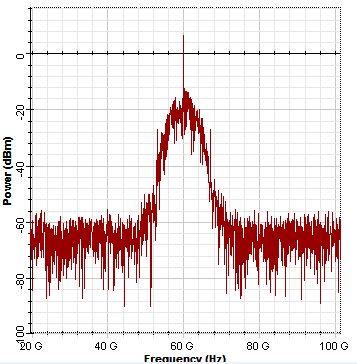
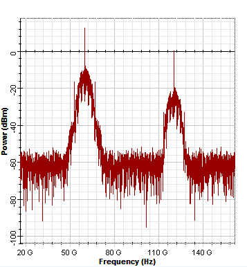
Dear Mohamed,i share my simulation result.please see the attachment(snapshots) one by one start from 1) photo-diode output 2)output of electrical multiplier (supposed to be electrical mixer),this multiplier is driven by 60GHz sinusoidal signal and one input from photo-diode.I look forward to your valuable comments to clear it whether it is working like a “ELECTRICAL MIXER”!!! .
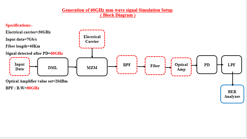
Thank you for the reply.sometime i get the worse BER value =<10-2 and this value changes with every run(slightly), i mean BER is not stable and unable to get a reasonable BER value.Please attached herewith the block diagram for more understanding.I look forward to your valuable suggestion.
Dear Zulfiqar,i still have not started work on digitization.I will start simulation in few days and will be in better position to explain you the use of ADC and DAC components in simulation.