
Base
| Full Name | Sasha |
| Organization | FIT |
| Job Title | student |
| Country |
Forum Replies Created
Hello all,
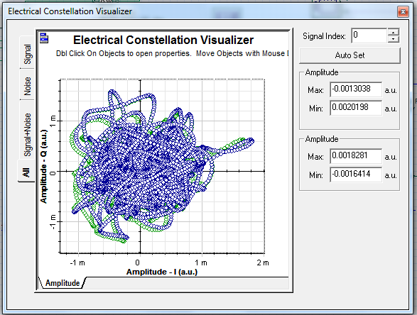
I implemented the Coherent Optical Transmission Optical System given in optiwave tutorial.
I got the different constellation diagram at the receiver.
Can anyone please help me out.
Thanks in advance.
Hello all,
I attached a file here. Please take a look at it.
Thanks in advance.
Hi Alitsu,
I am working in Optisystem version4 and it is available in my school. You can find the file QAM – Transmitter and Receiver.osd in samples library. I will upload the file when I am in school.
Thanks in advance.
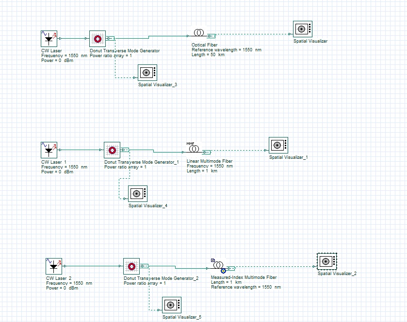
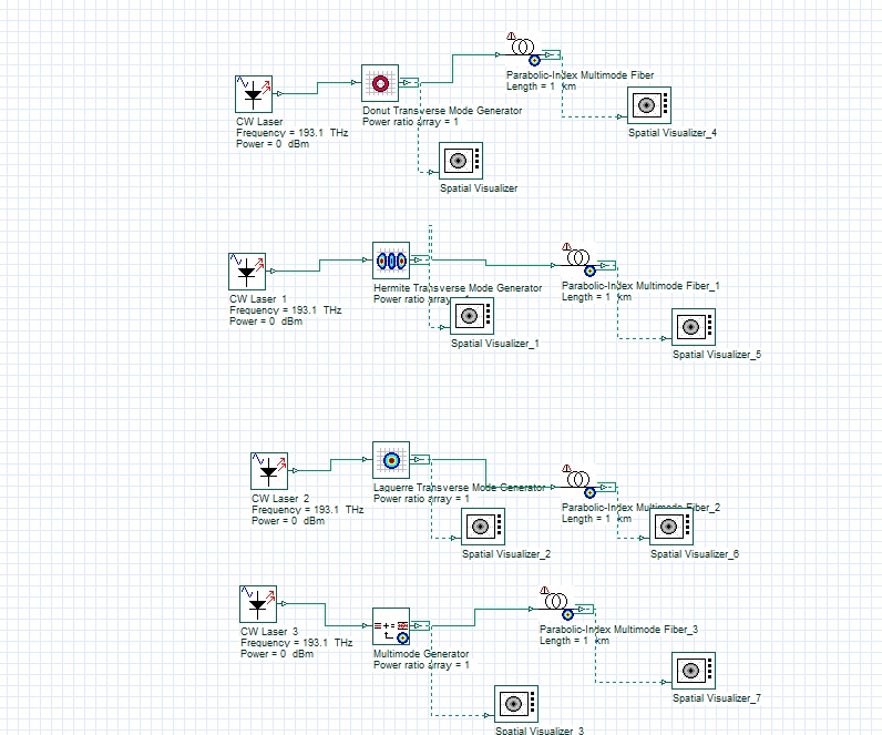
I used different refractive index profiles for SMF and MMF.
I am attaching the spatial visualizer report calculation and a picture of the file .
I am attaching the osd file.
Attachments:
Hello all,
I tried using the donut mode generator and transmitted one mode (0,0) through the Measured index multimode optical fiber and I got multiple modes at the output of the fiber. Totally I got 0 to 49 modes. When I saw the spatial visualizer report calculation, I got list of output nodes and power of the nodes. But when I viewed the output in spatial visualizer, mode 0 and 1, mode 6 and 7, mode 27 and 28, looks like same at the output screen.
Can anyone please clarify ?
I am attaching the spatial visualizer report calculation and a picture of the file and osd file.
And also I used the single mode fiber and linear multimode fiber and I got the output.
In single mode fiber, I got only mode 0 as output even when I transmitted more than one mode.
In multimode fiber, I got the output modes what I have transmitted at the input.
When I saw the donut mode component description, it converts the single mode into multiple modes.
This multimode conversion is happening at the measured index multimode fiber.
Why this conversion is not working in Linear MMF and SMF?
Thanks in advance.
Hello Arsha,
The incoming signal to be switched is split between the arms of the interferometer. The interferometer is balanced so that, in the absence of a control signal, the incoming signal emerges from one output port. The presence of a strong control pulse changes the refractive index of the medium. A change in the index adds a phase shift between the two arms of the interferometer, so that the incoming signal is switched over to another output port.
This explanation is given in the paper. Where as in normal MZI, the outputs are not switched.
Regards,
Sasha
Thank you Bryan.
Hello Sajad,
Try to uninstall the optisystem, and install it again.
Hello Hoat,
Can you explain your problem a little bit more?
Hello Harsh,
To get the 2D results, you have to do 2D simulation. I tried the tutorial in Optisystem13 version. So it is not possible for you to open in lower version.
Regards,
Sasha
Hello Raja,
For your second question, I think it is the overlapping of the two signals (i.e you can check the time duration of the signal).
Regards,
Sasha
Hello Garima,
In your system, the output of Electrical Subtractor to Oscilloscope visualizer is ‘0’. You have only noise at the output.
From the CW laser, I saw the output signal using OTVD gives 10e^6 signal. When you split the signal and sending it to photo detector,you got the two 5e^6 as output with some noise. Finally you used the subtractor, so you got the ‘0’ as signal output with some noise. Till this, your system is working. But What output are you expecting?
Regards,
Sasha