Optiwave software can be used in different industries and applications, including Fiber Optic Communication, Sensing, Pharma/Bio, Military & Satcom, Test & Measurement, Fundamental Research, Solar Panels, Components / Devices, etc..
OptiSystem is a comprehensive software design suite that enables users to plan, test, and simulate optical links in the transmission layer of modern optical networks.
OptiSPICE is the first circuit design software for analysis of integrated circuits including interactions of optical and electronic components. It allows for the design and simulation of opto-electronic circuits at the transistor level, from laser drivers to transimpedance amplifiers, optical interconnects and electronic equalizers.
OptiFDTD is a powerful, highly integrated, and user friendly CAD environment that enables the design and simulation of advanced passive and non-linear photonic components.
OptiBPM is a comprehensive CAD environment used for the design of complex optical waveguides. Perform guiding, coupling, switching, splitting, multiplexing, and demultiplexing of optical signals in photonic devices.
OptiFiber The optimal design of a given optical communication system depends directly on the choice of fiber parameters. OptiFiber uses numerical mode solvers and other models specialized to fibers for calculating dispersion, losses, birefringence, and PMD.
Emerging as a de facto standard over the last decade, OptiGrating has delivered powerful and user friendly design software for modeling integrated and fiber optic devices that incorporate optical gratings.
OptiConverge is a collaborative integration framework that seamlessly combines two or more Optiwave products (e.g., OptiSystem, OptiSPICE, OptiFDTD, etc.) and other third party products into unified solutions. Designed to streamline complex workflows, it empowers users to achieve their goals faster by harnessing the collective power of our trusted Optiwave tools.
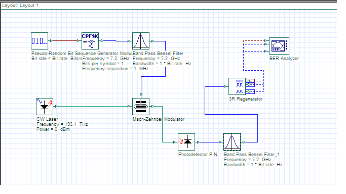
Thank you ranjeet for the related article. i think i should design the CPFSK and MSK modulator rather than using inbuilt components only then i will be able to decode.
Try reducing bit rate from 40Gbps to 40/No of channels. As i have seen in single channel DQPSK if we increase bit rate above 40Gbps response is not good.
As i am in office right now. but i would like to ask what parameters u have set for the layout window. try setting sequence length 1024 and samples per bit 64. Also reduce the bit rate for each channel to 10Gbps. How many channels are there in your designed mux? try solving with the given parameters.
Thanks
Sanjeev
Thanks for your kind feedback sir,
I have already done this but even then the problem exists. i have already learnt this thing. there is some other problem as PRBS bit rate script does not change my results.
I will always suggest plotting 2D Graphs and merging the response of all the receivers and it will show you the difference.
Thanks and Regards
Sanjeev Kumar
Hello everyone ,
the best way to take the snapshot of your design is as below:
1) From the layut options just hide the grids and your layot will be more clear for takng snapshot.
2) Now hide the project browser and Component browser and also hide the components description more clear vision of your design.
3) Now compress your design so that design takes less space and take snapshot using snipping tool.
4) save the snip and without grid it will be more clear and in MS word u can change the color contrast and brigtness etc to clear yout layout snip.
Thanks and Regards
Sanjee Kumar