Base
| Full Name | Salwa Mostafa |
| Organization | faculty of electronic engineering |
| Job Title | lecturer |
| Country |
Forum Replies Created
Hi Heitor Galvao
Where is the DCF component in optiwave library ?
Thanks in advance
i recommend this course for you also Fiber Optic Communication – Agrawal 4th edition
http://eu.wiley.com/WileyCDA/WileyTitle/productCd-0470922826.html
Good Luck
Attachments:
it’s working now. Thanks Damian very much for your help
Hi Damian
i used white light, but i have a problem in the first WDM mux .
range of wavelength used 1550–1557.8 with .8 spectral width.
which bessel filter center frequency and bandwidth for white light is appropriate.
Thanks in advance.
Hi Damian
what i mean when i made sweep range and try to draw it Vs. BER the first run result is the blue line ,when i made a second run for the same setting the red line produced. how can i reduce this so much change in results ?
can you please answer my question in the fourth replay
Thanks Damian very much.
Attachments:
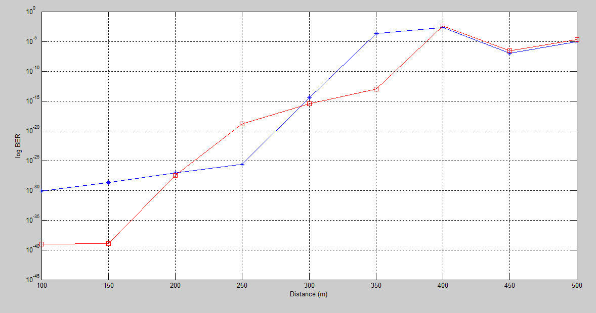
when i make sweep range every time i run the project the BER result is different .(different graphs (BER VS. range) ) ? how can i realize the appropriate system result ?
Hi Damian
i used white light, but i have a problem in the first WDM mux .
can you check if the bessel filter center frequency and bandwidth is appropriate.
Thanks in advance.
Thanks Damian very much.
Hi Damian
i want to clarify the following points to me
1- how you increased the power dramatically for the White Light source.
2- how you determine the appropriate center frequency and band with (Bessel filter) for the project.
3-is there any simulation examples for using MIMO technique
sorry for many questions but i need to understand
Thanks in advance
Hi Damian
I appreciate your help.
Thank you very much indeed.
Hi Damian
i can’t figure where is the different in frequency between first 1:12 WDM Demux and first 3:1 WDM MUx
Frequency[0] 1555.6
Frequency[1] 1556.2 in first WDM Demux
Frequency[2] 1557.8
in WDM MUX Frequency[0] 1555.6
Frequency[1] 1556.2
Frequency[2] 1557.8
the same thing at receiver side.
Hi Damian
i tried to change the sample rate in global mode but its close. also i changed the sample rate in white light to 2.5 Thz but it didn’t work.
can you tell me how you calculate the bandwidth ?
Do you mean changing the center frequency of PIN photo-detector ?
also i change the band with in LED to 2.5 THZ but it didn’t work .
if you tried and worked with you please attach the modification.
Thanks in advance
hi Damian
i used white light source but it didn’t work as attached. can you check it ?
in my project i use spectral width between each channel equal to .8 nm and i need 20 channel , i tried to increase the bandwidth of LED transmitter to 16 nm but it didn’t work.
thanks in advance
thanks very much jaffar for your help
Hi jaffar
Thanks for your help.
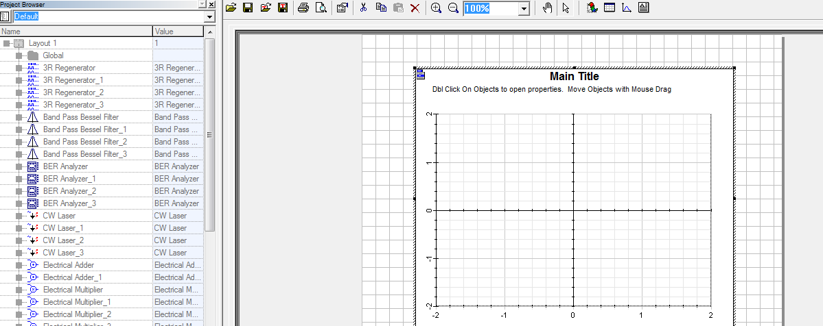
but i have a problem in drawing when i try to drag object to the 2D graph X-axis. its closed like in atttached image
Can you tell me how i can do that using matlab ?
Thanks in advance