
Base
| Full Name | Idahor Emmanuel |
| Organization | University of Hertfordshire |
| Job Title | Student |
| Country |
Forum Replies Created
I actually cant… from 65536, the next number you can put is 131072…. you cant type 102400, it jumps to 131072 automatically.
Yes i have checked and i kinda fixed it… I fix one problem and another pops out. Its all part of the learning process i guess. I was able to call it as alitsu suggested but im having an error with my OutputPort1. From calculating the matlab component. The outputPort1 is the error now.
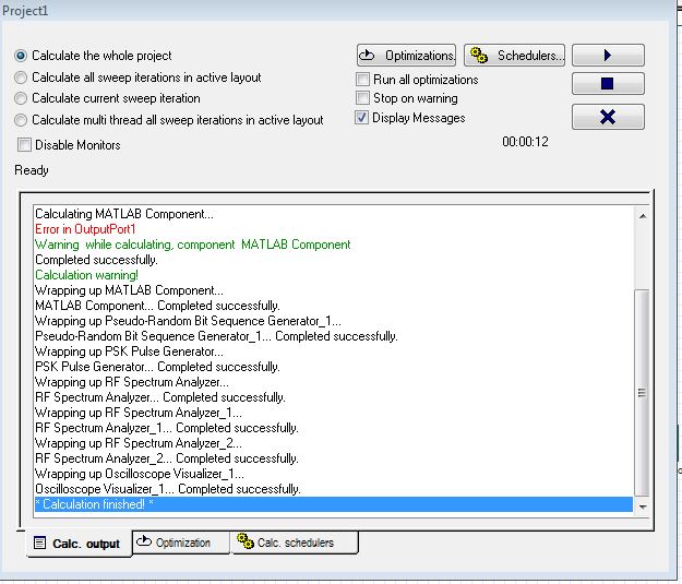
Yes thats the same thing i saw it … and it kept giving me see error. i attached the system. and am getting the same error.
Attachments:
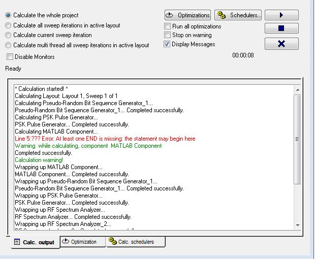
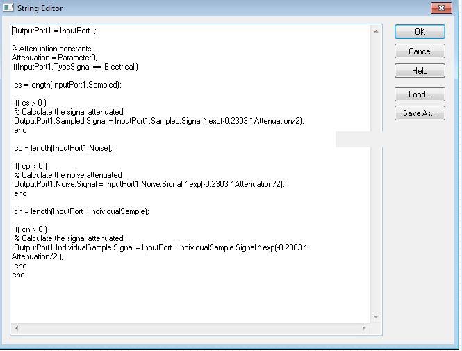
Thank you so much.. I have defined the parameter’0′.. and the error changed to a different thing. Now its saying an ‘end’ is missing in the code. I have checked and the number of end is correct… anyhelp please? i attached a picture of the error which i get… thanks
Attachments:
The two matlab components represent the OFDM modulator and demodulator…. Am trying to learn my way around optisystem so am just trying to understand how everything works, but i think i figured the early error out but there is a little issue.. the matlab workspace from the matlab component isnt producing any result from the matlab file even if the calculation was successful. So am not too sure the matlab component is working. I attached the working file … but the matlab workspace isnt producing any results. Can u help please?
Attachments:
I have gone through most of it .. and thats how i was able to get a basic idea about it. It calls the matlab from optisystem but it has an undefined error.. thats what i dont understand.
Thanks… Im having an undefined error of “parameter” when optisystem calculates the matlab component with electrical signal. i have attached the files for i have been facing the same error for more than a week.
Attachments:
HI,
I have tried co simulating my matlab code on optisystem, and it isnt co simulating… I have attached both files and tried to call it from optisystem and changed my matlab file but it isnt working. It pops an error from the matlab calculation saying undefind name ‘channel’.. The matlab code works fine and i do not know what next to do for am really confused. Thanks
Attachments:
Thank you so much for your reply.. How do i call the input to be received in optisystem? I am aware i have to change the ofdm modulator and demodulator and replace em with matlab components… calling it from optisystem is a bit tricky and i cant find my way around it. thanks
okay thanks.. yes i have written the Matlab code and it works fine. I’m attaching both files now.
Attachments:
Thank you so much alitsu for your support… you have really helped me in understanding the basic design on optisystem. Lastly I want to test a matlab file on the system. Is there any way of calling matlab on optisystem? I tried it by watching the tutorial video but not sure its working properly, because it says undefined matlab file.
Thank you alitsu for your prompt reply. I didnt get the explanation earlier, thanks for explaining better. I simulated the system and it was giving me a calculated error with the NRZ pulse generator making the constellation not to work. I have also tried using the constellation on the transmiter side and it gives the same error. Any reason to why this is happening?
Thank you so much for your reply… I used two forks at the output of my ofdm demodulator. and one of the forks connected to the input of my PSK decoder as mentioned by you but the other fork which has two outputs can’t be connected to a pulse generator (NRZ pulse generator) that has only one input and one output, and the Electrical constellation visualizer has 2 inputs. where do i connect the other input of the second fork been connected to a pulse generator?
The connection is attached
Attachments:
hi, please help with these questions.
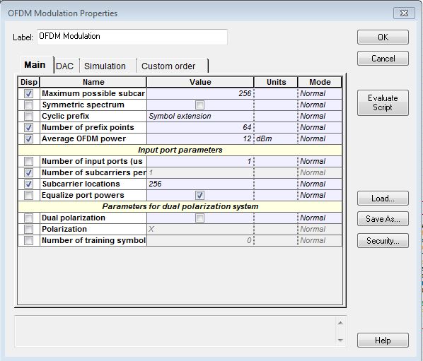
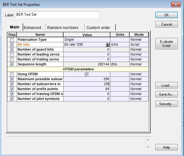
In capture1, how can i change the number of subcarriers per port to 256 assuming i want to use just 256 subcarriers out of 256 subcarriers.
In Capture2 how does the bit rate and the sequence length work?
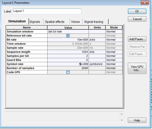
In capture4 i understand that the symbol rate is half of the bit rate, but the other parameters are quite confusing like sequence length.
Attachments:
Thanks Alistu for the effort, what i tried doing is connecting directly without optics, and the time window for its calculation is longer. when you run the simulation, it takes more time for its calculation. And i dont want to use 256 subcarriers out of 512. I want to use just 256 subcarriers out of 256.. is it possible to do that in the OFDM blocks… i have connected directly without optics it takes more time for its calculation. I attached the file below.