
Base
| Full Name | NURUL HAMIDA |
| Organization | universiti teknologi malaysia |
| Job Title | student |
| Country |
Forum Replies Created
Hi Sara..
Ok, I see.
Then, what kind of signal that you use for every channel, I mean such as WiFi signal or modulation signal or anything else?
Hello Sara
I would like to ask you.
How you differentiate CO OFDM signal for each channel.
It’s in terms of cyclic prefix or no pf subcarrier or others?
Hi, Marc…
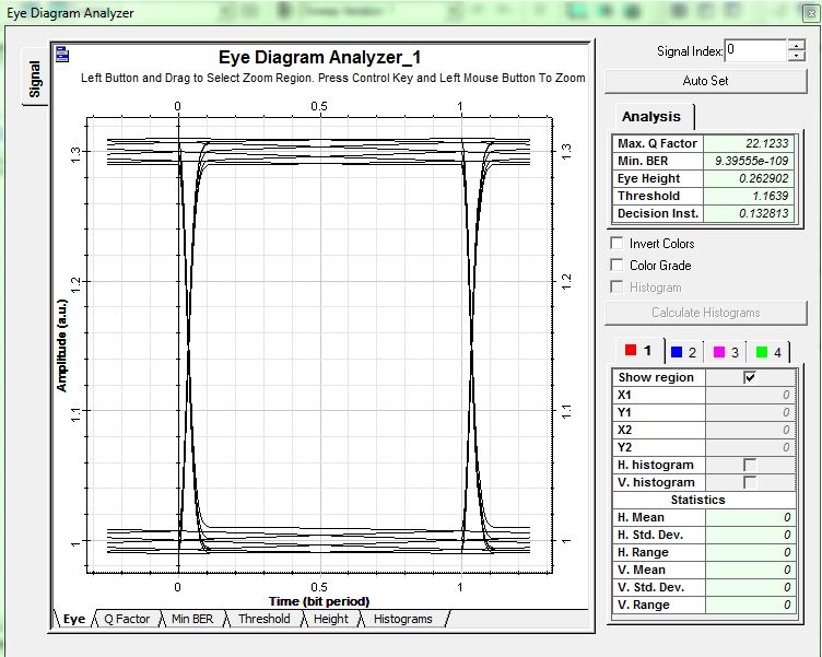
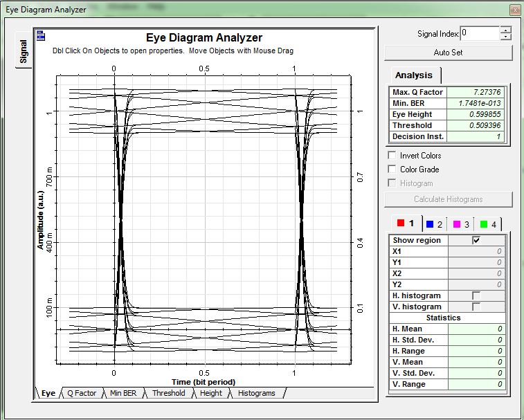
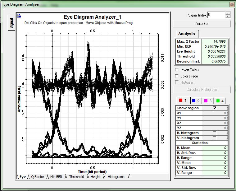
When I decrease the number no samples, the result shows an improvement. But, I’m still don’t know how to pick the exact value of no of samples. Can you help me?
Attachments:
Hi Marc Verreault
But I’m still confusing about the black rectangle in the up and down of the eye diagram.
Attachments:
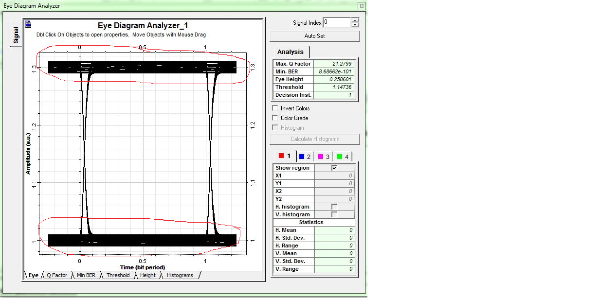
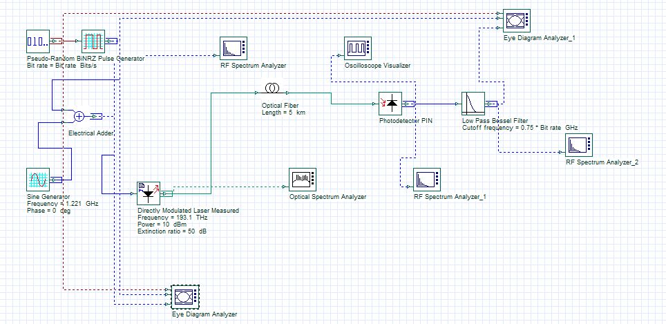
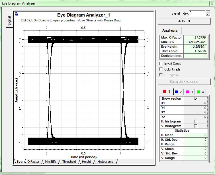
Down here are the design set up and the output of eye diagram at back to back (BTB) and at receiver (RX)
Hi, Marc Verreault…
Sorry for all the errors
Since the file exceeded the maximum file size allowed, I’m just giving the snapshot of the eye diagram result
Attachments:
Hi, Marc Verreault.
Now I’ve understood it..
Thanks a lot.:)
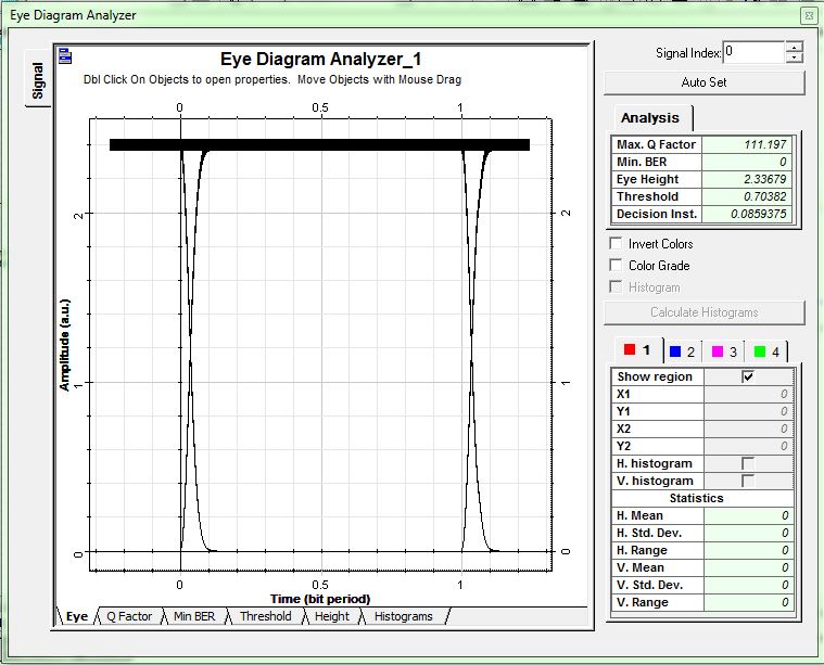
Hi, Marc Verreault…
Since the file exceeded the maximum file size allowed, I’m just giving the snapshot of the eye diagram result.
Thanks Naba krushna Sabat…:)
Hi Naba krushna Sabat..
Ok, right now i know about one of the OptiSystem 7 behaviour. Indeed, i am using Optisystem 7.
Thanks.
Hi Damian Marek,
Is there any threshold for sine wave?
Hi K. Esakki Muthu.
I have checked the bit rate. The PRBS bit rate was same with global bit rate. The result that I got as attached down here.
Attachments:
I have using OptiSystem 7 and Windows 7. But, the project browser are disabled
In the simulation, how do we know that the component is attached to the voltage or current source?. The sine generator component parameter did not mention to choose voltage or current. Currently, I am using OptiSystem 7.0
Thanks a lot Damian Marek…:)