Optiwave software can be used in different industries and applications, including Fiber Optic Communication, Sensing, Pharma/Bio, Military & Satcom, Test & Measurement, Fundamental Research, Solar Panels, Components / Devices, etc..
OptiSystem is a comprehensive software design suite that enables users to plan, test, and simulate optical links in the transmission layer of modern optical networks.
OptiSPICE is the first circuit design software for analysis of integrated circuits including interactions of optical and electronic components. It allows for the design and simulation of opto-electronic circuits at the transistor level, from laser drivers to transimpedance amplifiers, optical interconnects and electronic equalizers.
OptiFDTD is a powerful, highly integrated, and user friendly CAD environment that enables the design and simulation of advanced passive and non-linear photonic components.
OptiBPM is a comprehensive CAD environment used for the design of complex optical waveguides. Perform guiding, coupling, switching, splitting, multiplexing, and demultiplexing of optical signals in photonic devices.
OptiFiber The optimal design of a given optical communication system depends directly on the choice of fiber parameters. OptiFiber uses numerical mode solvers and other models specialized to fibers for calculating dispersion, losses, birefringence, and PMD.
Emerging as a de facto standard over the last decade, OptiGrating has delivered powerful and user friendly design software for modeling integrated and fiber optic devices that incorporate optical gratings.
OptiConverge is a collaborative integration framework that seamlessly combines two or more Optiwave products (e.g., OptiSystem, OptiSPICE, OptiFDTD, etc.) and other third party products into unified solutions. Designed to streamline complex workflows, it empowers users to achieve their goals faster by harnessing the collective power of our trusted Optiwave tools.
Is there any option to define electrodes in optiFDTD. My requirement is to control my photonic device using electric field. I have done it in optiBPM. Furthe I want to do it in optiFDTD. Please share the possibility of doing same in optiFDTD. Thanks in advance…
Consider I am having a DC electric field, which can switch its state(either 0 V or 5 V) with the speed of 1 MHz. How can I apply this electric field to MZI electrodes and capture the response. From this I can test how fast the MZI is responding to the external electric field. Obviously the speed of light propagation is higher than the speed of electric field. But, i need to capture the response of MZI for the speed of external electric field. In this regard I need your help..
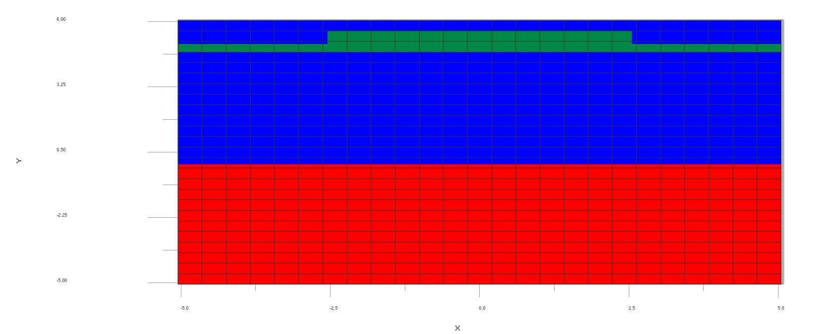
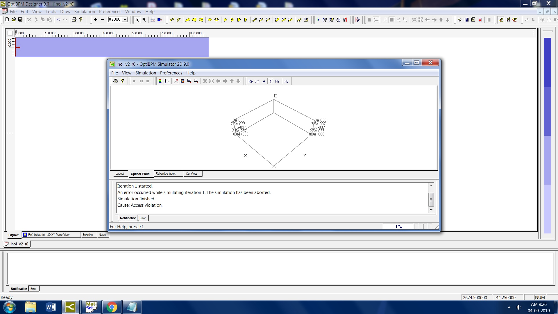
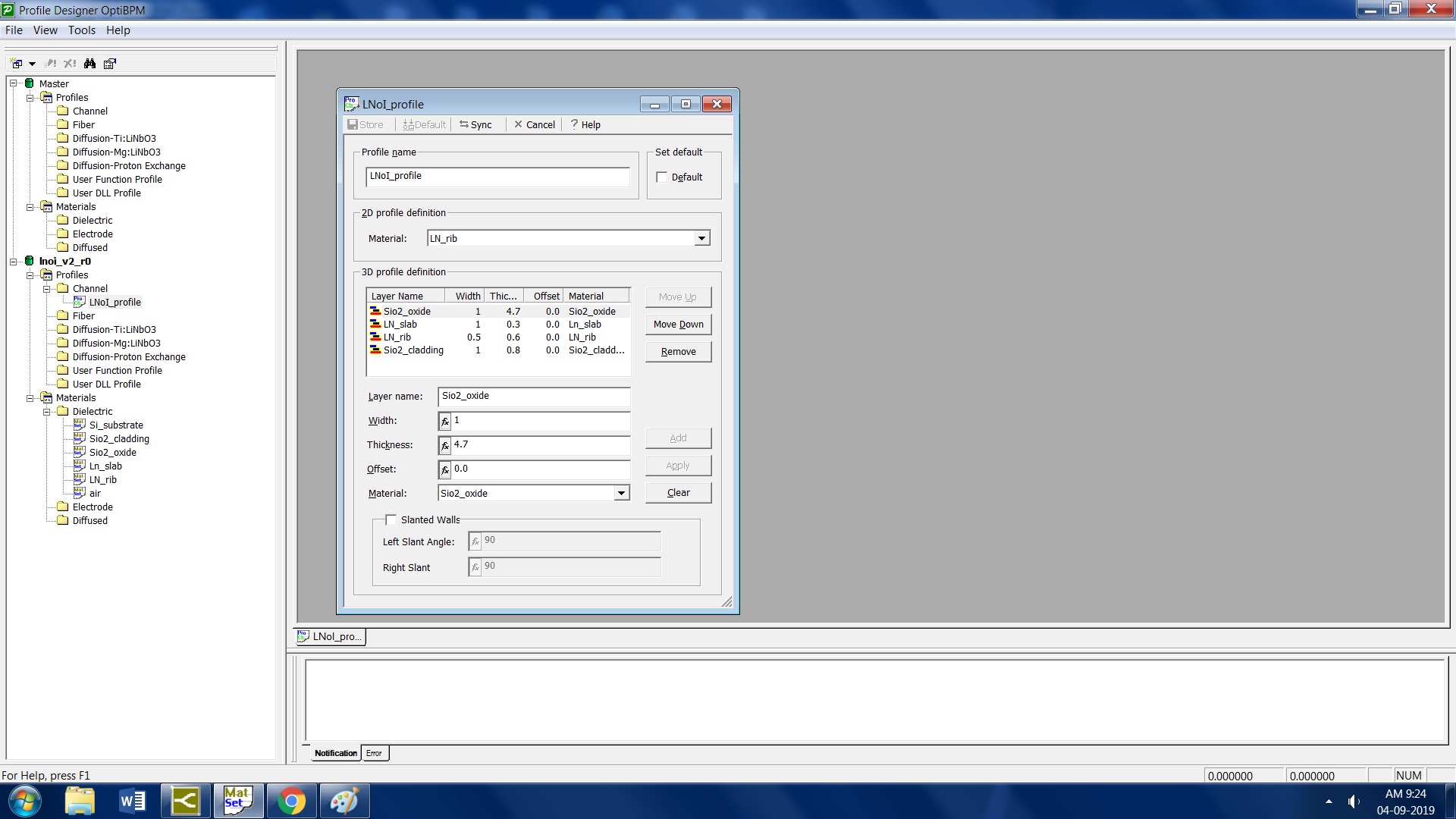
The LN on insulator(Sio2) is used for low loss and better confinement. I have attached the files. Please suggest some ways to create layered profiles. I have tried using channel profile and adding layers in substrate option. The structure is created but it shows error while running the simulation. Often it shows violation error..
Thank you for your great answer. I have found in a sample file of OptiBPM ie. Magnesium doped waveguide is placed on top of the Titanium doped lithium niobate. The waveguide model is working, but the output electric field is decreasing in magnitude if we increase the length of the waveguide. I also tried to configure as directional coupler, but there is no coupling between two waveguides. We are mainly focusing on MgO:LiNbO3 wafers to develop our optical devices, hence I require this Mg doped LN waveguide.