Optiwave software can be used in different industries and applications, including Fiber Optic Communication, Sensing, Pharma/Bio, Military & Satcom, Test & Measurement, Fundamental Research, Solar Panels, Components / Devices, etc..
OptiSystem is a comprehensive software design suite that enables users to plan, test, and simulate optical links in the transmission layer of modern optical networks.
OptiSPICE is the first circuit design software for analysis of integrated circuits including interactions of optical and electronic components. It allows for the design and simulation of opto-electronic circuits at the transistor level, from laser drivers to transimpedance amplifiers, optical interconnects and electronic equalizers.
OptiFDTD is a powerful, highly integrated, and user friendly CAD environment that enables the design and simulation of advanced passive and non-linear photonic components.
OptiBPM is a comprehensive CAD environment used for the design of complex optical waveguides. Perform guiding, coupling, switching, splitting, multiplexing, and demultiplexing of optical signals in photonic devices.
OptiFiber The optimal design of a given optical communication system depends directly on the choice of fiber parameters. OptiFiber uses numerical mode solvers and other models specialized to fibers for calculating dispersion, losses, birefringence, and PMD.
Emerging as a de facto standard over the last decade, OptiGrating has delivered powerful and user friendly design software for modeling integrated and fiber optic devices that incorporate optical gratings.
OptiConverge is a collaborative integration framework that seamlessly combines two or more Optiwave products (e.g., OptiSystem, OptiSPICE, OptiFDTD, etc.) and other third party products into unified solutions. Designed to streamline complex workflows, it empowers users to achieve their goals faster by harnessing the collective power of our trusted Optiwave tools.
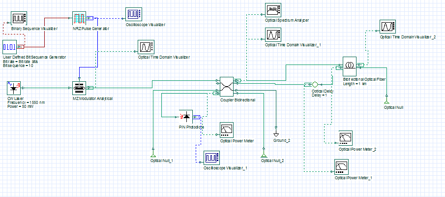
The purpose of my simulation on Optisystem that i get results similar to practical design that I made, Which is to measure the backscattered light returning from the fiber as value and the delay time to be able to get the OTDR analysis correctly and to calculate the best pulse width with best resolution to get a better analysis for the fiber, So what i am doing now is configuring how my design is going to work.
Dear Ahmed,
I am so thankful for your help, I managed to receive the backscattered signal but its not delayed as it appears on the visualizer on the same exact time of the input signal as it is supposed that I see a time delay in my simulation between the input and output signals but only amplitude of the signal is affected, So can you tell me why is that ??
Dear Ahmed,
Thank you for replying first, I already did so and tried to receive signal power at the output port of the coupler using Optical power meter connected to the PIN photodiode, But the optical power meter gives me received signal power = -100 dbm and only reads noise power and the photodiode don’t detect anything.