
Base
| Full Name | marvi grover |
| Organization | panjab university |
| Job Title | student |
| Country |
Forum Replies Created
yes Alistu..
in the system which you have attached, the function of fork is quite justified for the simulation purposes.
thankyou so much for the help.
regards
marvi
okk, thankyou Alistu.
actually i have seen ‘fork’ being attached in a lot of systems which have done simulation using optisystem. all of them have used it for the duplication of the input signal, but i think there must be some practical justification to the use of this component which i am not able to find. beacuse ultimately these systems have to be realized practically. CAn we ask Damian Marek about this??, may be he has some more knowledge.
please let me know if u find out out something about this.
i shall be really grateful.
Regards
Marvi
ok Alistu
thanx a lot for your help.
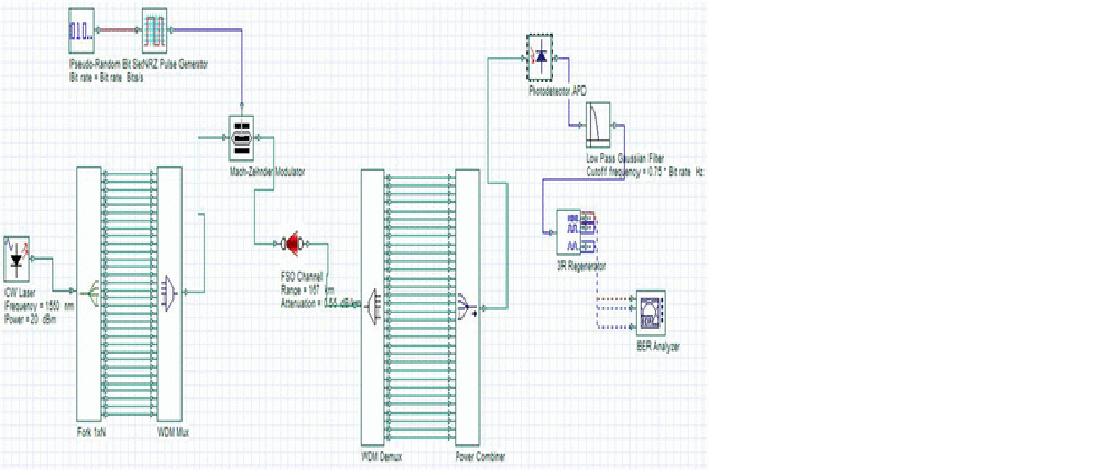
here is a new question i wanted to ask about the component ‘fork’ used in optisystem. what is the exact function of the fork. in the ‘help’ about the fork, it is written that it copies the input to multiple output port, but i have a doubt here, if the fork copies the input to the output, then the power of each signal at the output should be same as the input signal , i am attaching a screenshot of a system, refering to that….how can we give one signal of a particular power at the input and rceive many signals of the same power at the output????
is there some power multiplier or something like that present in the fork.
Attachments:
i think i have not used the array editor shown in the tutorial.perhaps that is the reason for this error but i am not able to find the array editor, how to open it ??
it is in matlab or optisystem???
yes alistu, thankyou so much
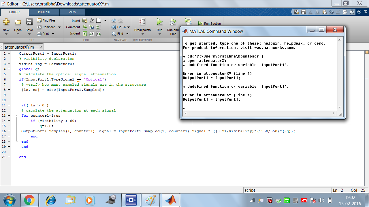
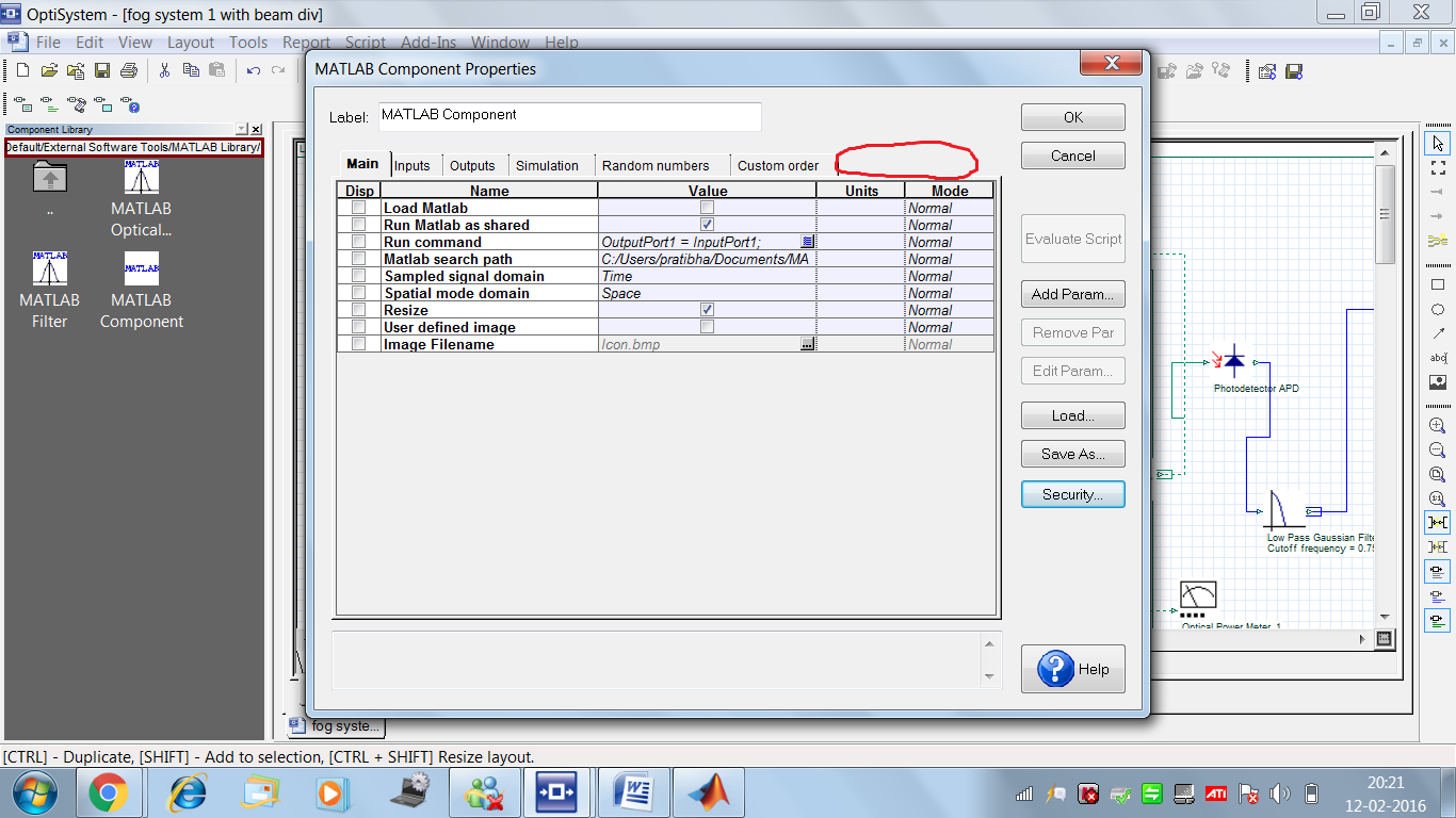
i was able to add the parameter but now i am getting error in my matlab code, i am the screenshots.
i am getting an error in the first line “outputport1=inputort1”
i read your reply for the same problem in the forum but m nt able to correct it. i am opening the program using tha command windoe only.
please have a look to find out what the prblem is.
thankyou
Attachments:
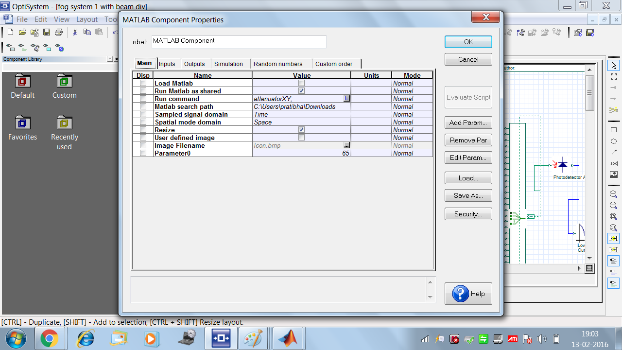
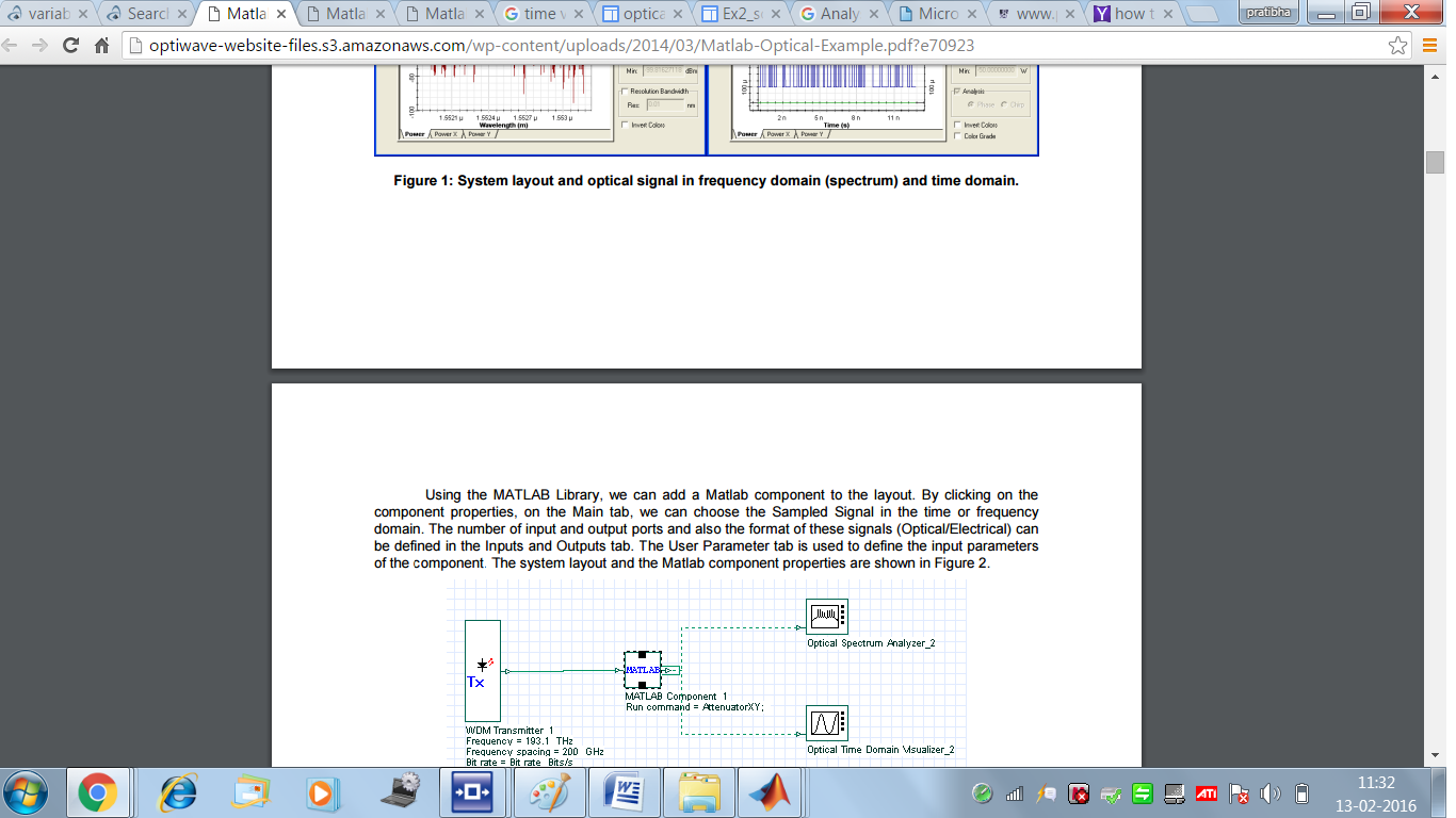
in the user manual about how to add matlab component ,it is written that the input parameters of the component have to be specified in the matalab component properties. so i think user parameter tab is neccessary to specify the input parameters which i will be using in my matlab code. i am attaching a screenshot.
Attachments:
hii alistu
i need some more help.
when i am including the matlab component in optisystem , and i click on its properties, i am not getting the ‘ user parameters’ tab in it, which is shown in the tutorial.
i am attaching the screenshot of it. please help me to get it
Attachments:
ok alistu . thankyou so much for your help.
yes alistu, i want the attenuation to change, but yes you are right, it is not possible to change it in the middle of calculation.
but is there some option available where i can specify the global parameter as a “variable” for example visibility as ‘v’, and then relate to a matlab variable, so that if i change the value of ‘v’ in matlab component, then this value of v is used in the formula for attenuation calculationin optisystem.
how do i relate a matlab variable to optisystem “variable”.
waiting for your reply
regards
marvi
thankyou so much Alistu.
in that system, the rain rate has been fixed at ‘2’, how can i make this value variable??? for example : the formula i want to implement is attenuation = (3.91/v)(1550/550)^-q , where v is the visibility in kilometers and q is some number. so i will write this formula in th script of attenuation, but i want the values of v and q to be variable, that is they change according to some condition which will be specified in the matlab component that i will be attaching before the FSO channel.
how can i do this??
please suggest me a solution
regards
marvi