
Base
| Full Name | Marvi grover |
| Organization | panjab university |
| Job Title | student |
| Country |
Forum Replies Created
Thank you so much 🙂
hello !!
Can anybody tell me how to code the attenuation due to scintillation effect in MATLAB. i need to use a MATLAB code and produce the same effect on the signal as done by enabling ‘intensity scintillation’ parameter in optisystem.
i shall be thankful to you
Regards
Marvi
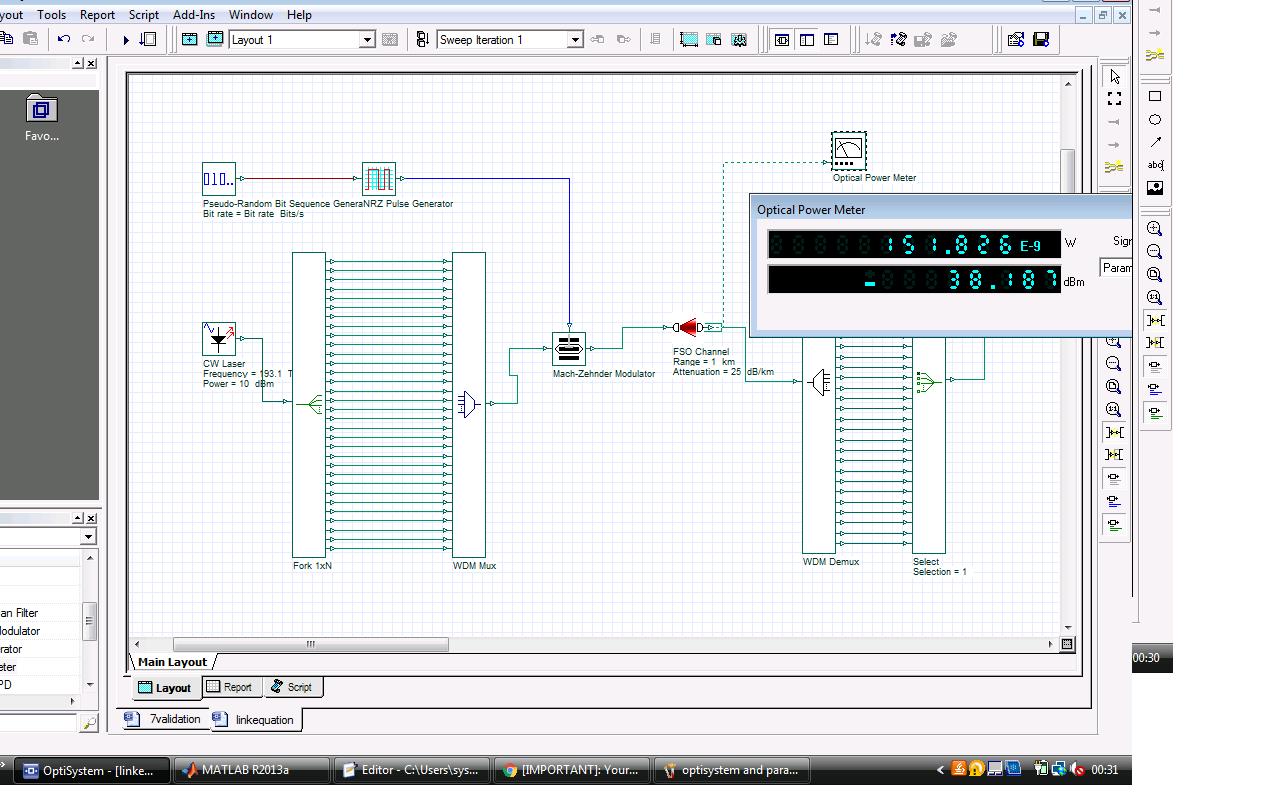
in this case the power calculated manually is same as that given by optical power meter.
Hello Aabid!!
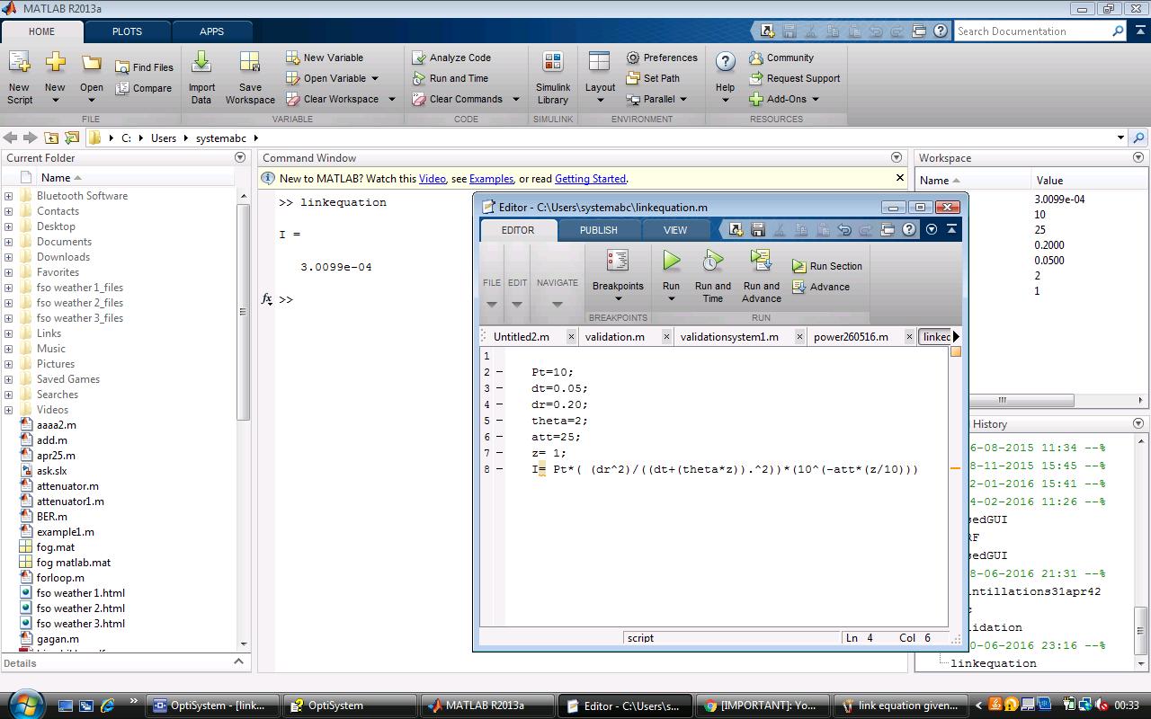
i got to know my mistake. i was using the transmitted power as it is in the manual calculation.
but my system had a MUX and modulator attached after the laser source which led to some power loss. so the actual power launched in th channel was less than 10dBm and this power was to be used in the calculation.
i hope i am able to make my point.
Regards
Marvi
i am getting it as -35.2144 dbm and optical power meter gives it to be -38.421
Aabid bashir Baba and Sidra Khan
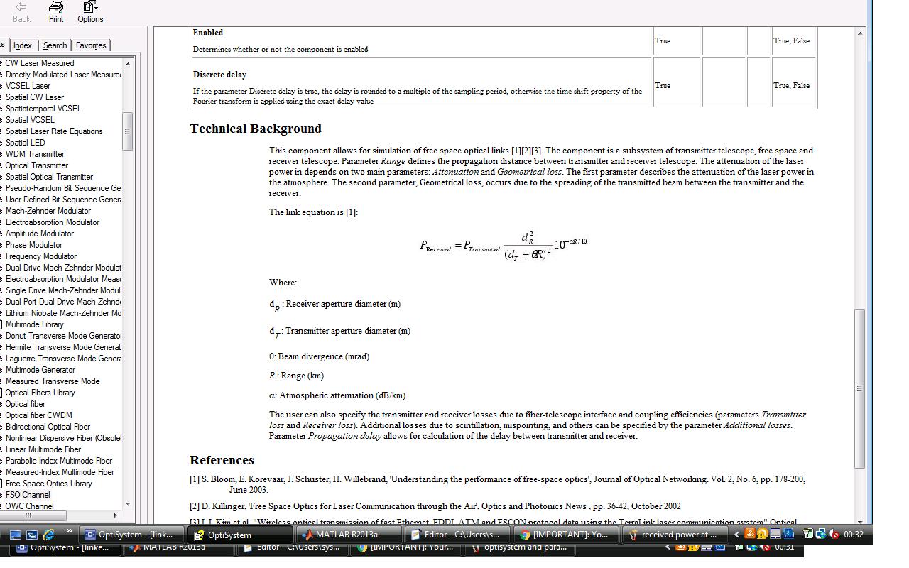
i am using the unit mentioned in the ‘help’ for the link equation i.e. meters for the transmitter and receiver aperture,
kilometers for the ‘range’, dB/km for the attenuation and milliradian for the beam divergence, transmitted power in dBm.
i think received power should be in ‘dBm’.
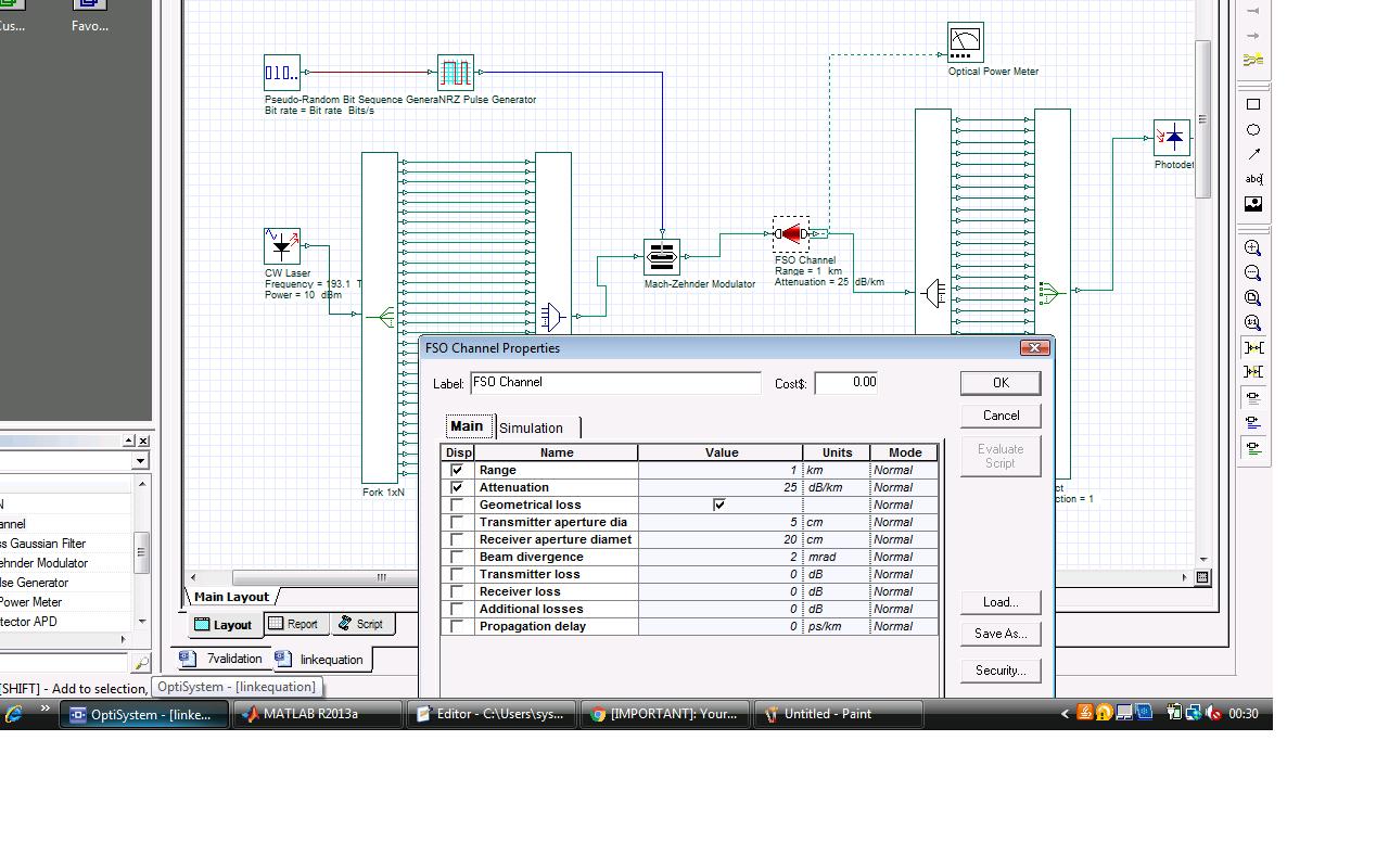
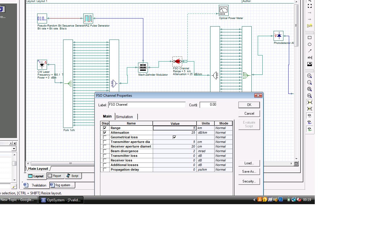
following parameters are used in the optisystem design.
transmitter aperture:0.05 meter
receiver aperture : 0.2 meter
transmitted power : 10 dBm
range : 1 kilometer
attenuation: 25 dB/km
beam divergence: 2 mrad
you can use these parameters and check the results manually. please let me know your result. i might be doing some mistake. i am also attaching the .osd file for the results given by optical power meter.
Attachments:
Thankyou so much for having a look.
i tried to connect the power meter after the ‘select’ component in my system, but the power still doesnt match with calculated one.
Sir
In the optisystem ‘help’ of ‘FSO component’ , a link equation is given to calculate the recieved power.When i am calculating the received power manually using this equation, the result does not match with that given by the optical power meter in optisystem. please tell me why is this happening. i am attaching the snippets of optisystem and parameters used and also the matlab code used to calculate the power manually.
please help me with this. i shall be really grateful to you.
Regards
Marvi
Thank you so much sir. I will look into these papers and revert back.
Regards
Marvi
the system used is attached here
Attachments:
thankyou so much everyone for your valuable suggestions. I will have a look into them.
Regards
marvi
Thankyou So much everyone….i’ll try the solutions suggested by you.
i am attaching the matlab file here.
Attachments:
yes …sure . iam attaching the osd file
Attachments:
this is the matlab file for the program